SpeedyBee F7 V3 50A stack
SpeedyBee released the third version of the SpeedyBee F7 50A stack. It has quite a number of changes and improvements. Some of the features are (almost) unique in the market. Lets take a short overview of them.
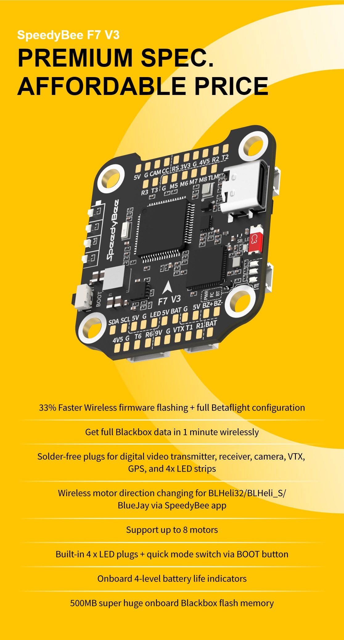
The gyro was changed from the end of the production MPU-6000 to the new trending Bosch BMI-270.
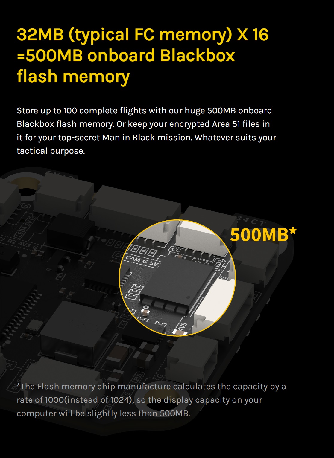
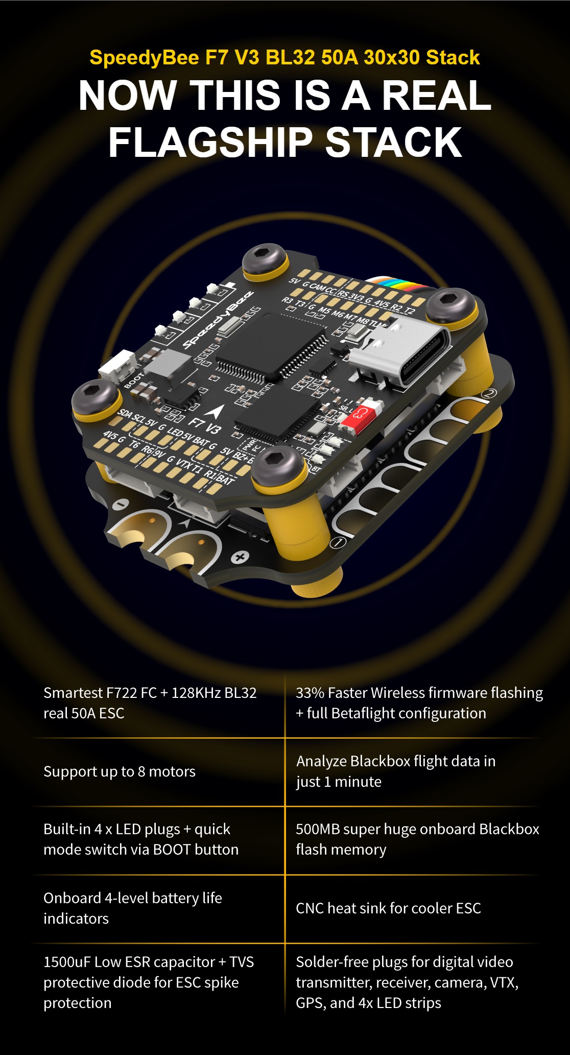
Blackbox chip size was increased from 16MB onboard data flash to enormous 500MB. It’s a half of Terabyte of log data! You could probably store a whole season Blackbox data on your SpeedyBee F7 V3 FC. That’s the biggest built in blackbox on a chip size in the market.
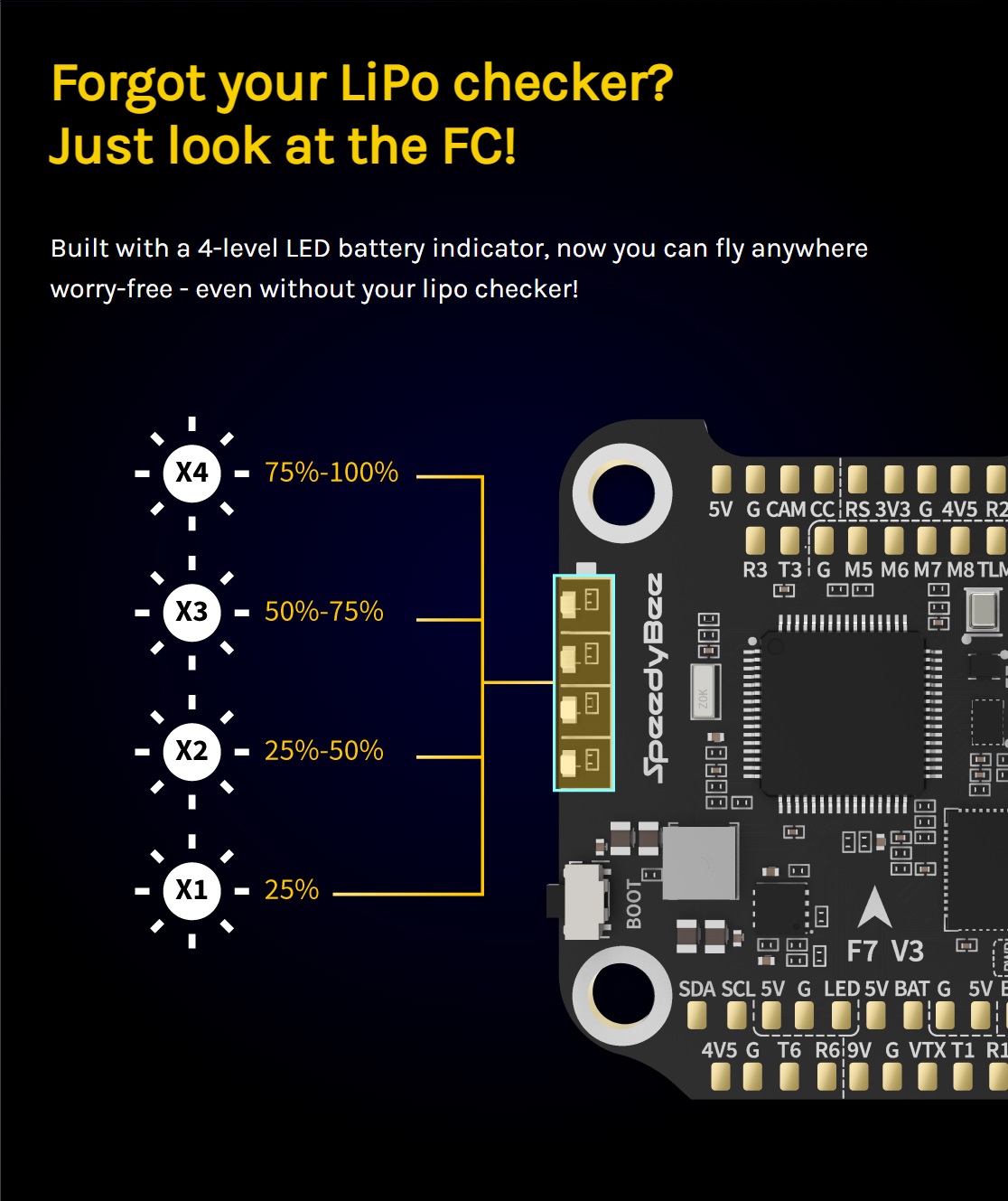
There is a battery voltage checker built in right on the FC board. 4 LED indicators show the battery charge state.
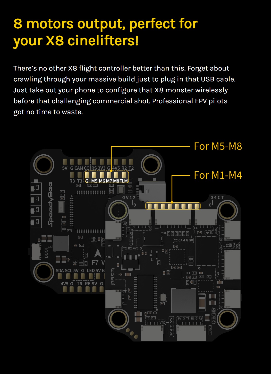
SpeedyBee F7 V3 also has 5 UARTS, I2C, BMP280 barometer, 8 motor outputs. The FC has 9V, 5V, 4.5V and 3.3V outputs to fit any needs.
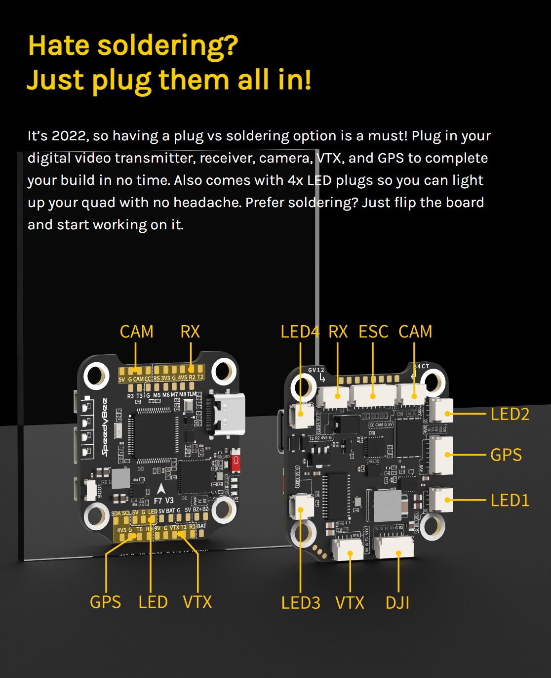
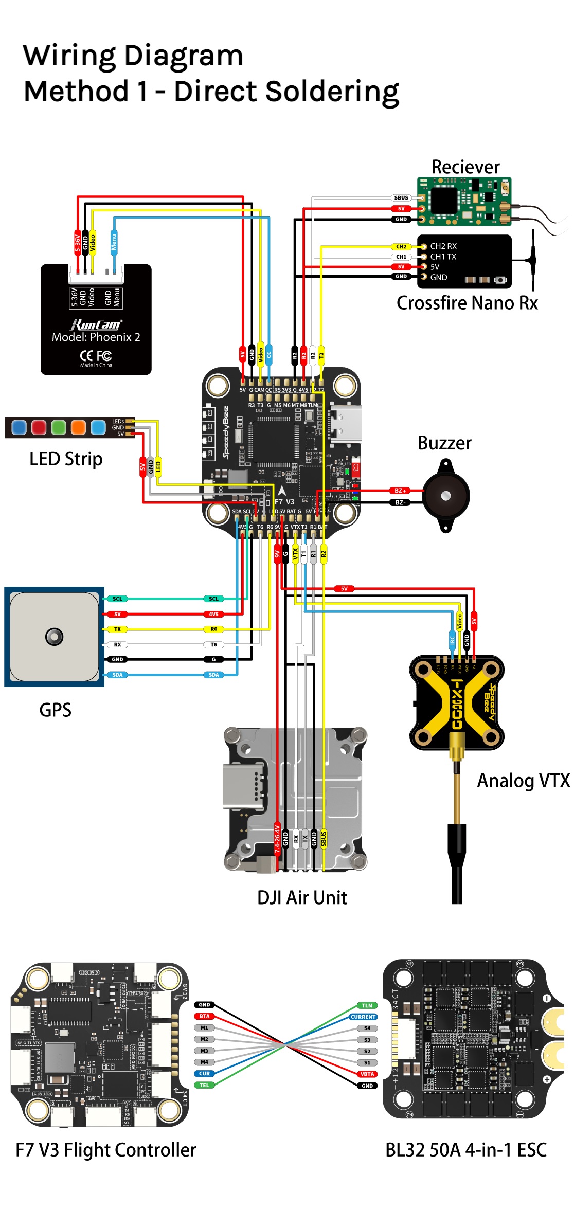
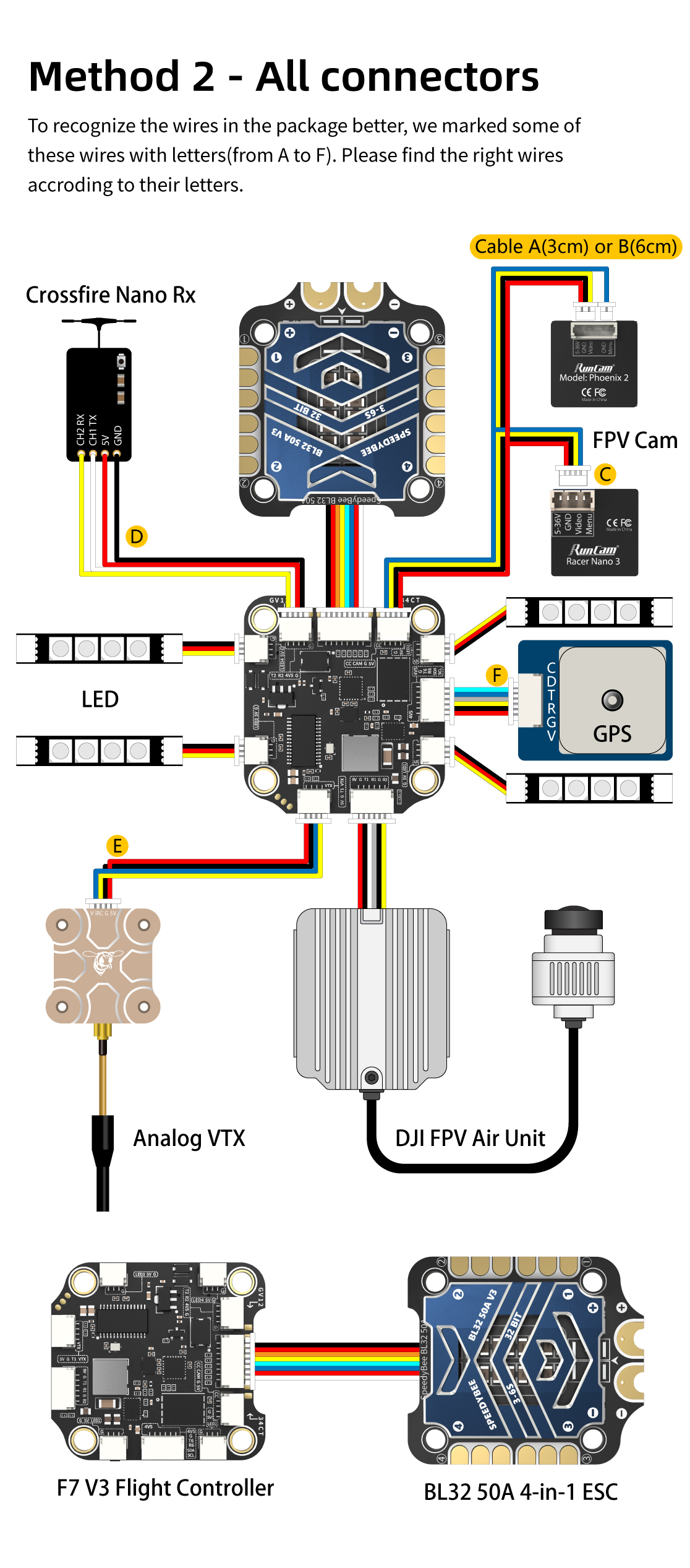
You can use solder pads or plugs for connecting the peripherals.
SpeedyBee F7 V3 50A is a premium specs stack with wireless features.
SpeedyBee F7 V3 FC and 50A ESC connection diagram
Available @
SpeedyBee: https://www.speedybee.com/speedybee-f7-v3-bl32-50a-30×30-stack/
Specfications
| Product Name | SpeedyBee F7 V3 Flight Controller |
| MCU | STM32F722 |
| IMU(Gyro) | BMI270 |
| USB Port Type | Type-C |
| Barometer | BMP280 |
| OSD Chip | AT7456E chip |
| BLE Bluetooth | Supported. Used for Flight Controller configuration |
| Flash FC Firmware Wirelessly | Supported. Please enter MENU > FC Firmware Flasher |
| Download/Analyze Blackbox | Supported.Please enter MENU > Blackbox Analyzer |
| DJI Air Unit Connection Way | Two ways supported: 6-pin connector or direct soldering. |
| Flash(for BlackBox) | 500MB |
| BetaFlight Camera Control Pad | Yes (CC pad on the front side) |
| Power Input | 3S – 6S Lipo |
| 5V Output | 10 groups of 5V output, three +5V pads and 1 BZ+ pad( used for Buzzer) on front side, and 6 +5V output included in the connectors on bottom side. The total current load is 2A. |
| 9V Output | 2 groups of 9V output, one +9V pad on front side and other included in a connector on bottom side. The total current load is 4A. |
| 3.3V Output | Supported. Designed for 3.3V-input receivers. Up to 500mA current load. |
| 4.5V Output | Supported. Designed for receiver and GPS module even when the FC is powered through the USB port. Up to 1A current load. |
| ESC Signal Pads | M1 – M4 on bottom side and M5-M8 on front side. |
| UART | 5 sets (UART1, UART2, UART3, UART4(For ESC Telemetry), UART6) |
| ESC Telemetry UART | R4(UART4) |
| I2C | Supported. SDA & SCL pads on front side. Used for magnetometer, sonar, etc. |
| LED Pad | Used for WS2812 LED controlled by Betaflight firmware. |
| Buzzer | BZ+ and BZ- pad used for 5V Buzzer |
| BOOT Button | Supported. [A]. Press and hold BOOT button and power the FC on at the same time will force the FC to enter DFU mode, this is for firmware flashing when the FC gets bricked. [B]. When the FC is powered on and in standby mode, the BOOT button can be used to controller the LED strips connected to LED1-LED4 connectors on the bottom side. By default, short-press the BOOT button to cycle the LED displaying mode. Long-press the BOOT button to switch between SpeedyBee-LED mode and BF-LED mode. Under BF-LED mode, all the LED1-LED4 strips will be controlled by Betaflight firmware. |
| RSSI Input | Supported. Named as RS on the front side. |
| SmartPort | Use any TX pad of UART for the SmartPort feature. |
| Supported Flight Controller Firmware | BetaFlight(Default), EMUFlight, INAV |
| Firmware Target Name | SPEEDYBEEF7V3 |
| Mounting | 30.5 x 30.5mm( 4mm hole diameter) |
| Dimension | 41(L) x 38(W) x 8.1(H)mm |
| Weight | 10.7g |
| Product Name | SpeedyBee BL32 50A 4-in-1 ESC |
| Firmware | SpeedyBee BL32 50A |
| Configurator Download Link | http://github.com/bitdump/BLHeli/releases |
| Continuous Current | 50A * 4 |
| Burst Current | 55A(5S) |
| TVS Protective diode | Yes |
| Heat Sink | Yes |
| External Capacitor | 1500uF Low ESR Capacitor(In the package) |
| ESC Protocol | DSHOT300/600 |
| Power Input | 3-6S LiPo |
| Power Output | VBAT |
| Current Sensor | Support (Scale=490 Offset=0) |
| Mounting | 30.5 x 30.5mm( 4mm hole diameter) |
| Dimension | 45.6(L) * 40(W) * 8.8mm(H) |
| Weight | 19.2g with heat sink |
-
 BetaFPV SuperG NanoTX – first dual diversity ELRS TX
BetaFPV, in collaboration with the ELRS developer team, has unveiled another first in the
BetaFPV SuperG NanoTX – first dual diversity ELRS TX
BetaFPV, in collaboration with the ELRS developer team, has unveiled another first in the -
 Radiomaster Pocket Radio
Radiomaster has unveiled its latest creation, the Radiomaster Pocket Radio, a compact but feature-packed
Radiomaster Pocket Radio
Radiomaster has unveiled its latest creation, the Radiomaster Pocket Radio, a compact but feature-packed