Restoring bricked Eachine ProDVR after failed firmware update
If your ProDVR is bricked after failed firmware update process, you can easily restore it by flashing firmware directly to the serial flash ship.
What you will need:
- Arduino Mini Pro atmega328 board. (16Mhz 5V, about 1.30$)
It is also possible to use Arduino Nano with atmega328 16Mhz (Possible variants on ebay: https://goo.gl/zd0twR, Banggood: https://goo.gl/MDmy3E)
- USB to Serial adapter. It can be FTDI, CH340G (just look for ones that support 3.3V , about 1.30$) (Possible variants on ebay: https://goo.gl/Ru7BXF)
- Thin wires for connecting Arduino and Serial Flash
Next parts are needed if Arduino outputs more than 3.3V on signal pins:
- Resistors for level divider 5k and 10k both (2 pcs of each value)
- Breadboard (not necessary, but very convenient)
Alternatively you can use SOP8 programming clip, so you will not have to solder the wires to the chip.
Software
- Flashrom programming utility (https://www.flashrom.org ). If your PC runs on Windows then I recommend to download already compiled windows version here: http://ra.openbios.org/~idwer/flashrom/mingw/ (Edit: link seems to be dead now, but we have it saved on Internet Archive: https://web.archive.org/web/20181112215901/http://ra.openbios.org/~idwer/flashrom/mingw/)
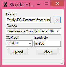
- XLoader to upload binary file to Arduino board (http://russemotto.com/xloader/ ) (Edit: link seems to be dead now, here is alternative link: http://www.hobbytronics.co.uk/download/XLoader.zip)
- Arduino firmware (frser-duino.hex) (download link: https://drive.google.com/file/d/0BxZ43kLDo-GFOWJnQ19HYWVZVmc/view)
- ProDVR firmware file (flash.hex) (download link: https://drive.google.com/file/d/0BxZ43kLDo-GFOVN4bUJRaEoxTms/view)
Procedure step by step
First you need to flash Serprog firmware to Arduino Mini Pro:
- Connect USB – TTL converter to Arduino Mini Pro board
- If everything is ok, You should see “FTDI” or “USB-SERIAL CH340” device in device manager
- Connect Arduino Mini Pro to USB-TTL adapter (check that your FTDI or USB Serial adapter uses 3v for powering)
- Start Xloader, open [fser-duino.hex] file, set the right com port and hit “Upload”.
Now You have Flashrom compatible programmer.
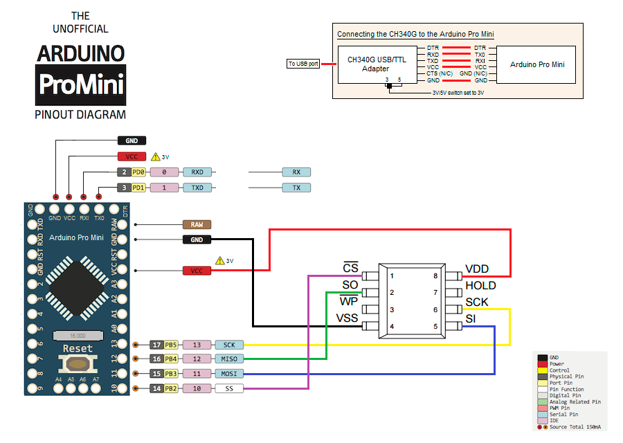
Connect ProDVR serial flash IC to the Arduino. Use supplied connection schematics. For this you need to lift a bit VCC pin of the serial flash to disconnect from the rest of the board electronics and solder 5 wires: VCC, GND, CS, CLK MOSI and MISO. Try to keep them as short as possible, about 10cm. Use small diameter wire.
Connection table:
FLASH CHIP – ARDUINO
VCC (pin 8 ) to Arduino 3.3V output (5V would likely kill the chip, be carefull)
GND (pin 4) to Arduino GND pin
CS (pin 1) to Arduino pin 10
DO (pin 2) to Arduino pin 12
DI (pin 5) to Arduino pin 11
Clock (pin 6) to Arduino pin 13

Schematics (only if Arduino outputs 3.3V signal levels):
Once connected, try reading the contents of flash IC by running this command:
mingw32-w64-flashrom-r1781.exe --programmer serprog:dev=COM10:115200 -c MX25L1605 --read test.hex
You should get similar output to this:
E:\My\RC\Flashrom>mingw32-w64-flashrom-r1781.exe --programmer serprog:dev=COM10:115200 -c MX25L1605 --read test.hex
flashrom v0.9.7-r1781 on Windows 6.2 (x86)flashrom is free software, get the source code at http://www.flashrom.org
Calibrating delay loop... OK.
serprog: Programmer name is "frser-duino"
Found Macronix flash chip "MX25L1605" (2048 kB, SPI) on serprog.Reading flash... done.
If everything goes OK by this far, you are ready to flash the firmware. To flash the device, start this command:
mingw32-w64-flashrom-r1781.exe --programmer serprog:dev=COM16:115200 -c MX25L1605 --write flash.hex
You should get similar output to this:
E:\My\RC\Flashrom>mingw32-w64-flashrom-r1781.exe --programmer serprog:dev=COM16:115200 -c MX25L1605 --write flash.hex
flashrom v0.9.7-r1781 on Windows 6.2 (x86)flashrom is free software, get the source code at http://www.flashrom.org
Calibrating delay loop... OK.
serprog: Programmer name is "frser-duino"Found Macronix flash chip "MX25L1605" (2048 kB, SPI) on serprog.
Reading old flash chip contents... done.
Erasing and writing flash chip... Erase/write done.
Verifying flash... VERIFIED.
You are done! Now reconnect serial flash chip Power pin to the PCB and try to power your ProDVR. Insert SD card and you good to go!
If you have questions or you need more details, then leave a comment below.
Created: 2018-06-19
Updated: 2020-11-15 – some links appear to be down. Alternatives provided
-
 ESC Firmware Guide
In this concise overview, we’ll explore the evolution of ESC (Electronic Speed Controller) firmware,
ESC Firmware Guide
In this concise overview, we’ll explore the evolution of ESC (Electronic Speed Controller) firmware, -
 List of brushless whoop/toothpick flight controllers
This is the list of brushless tiny whoop/toothpick style flight controllers with brief description
List of brushless whoop/toothpick flight controllers
This is the list of brushless tiny whoop/toothpick style flight controllers with brief description
Hello, i am having issue getting the flash software to see the connected chip. the wires are correct and the programmer is being detected just not seeing the chip. i also have another one which it can see but fails to erase when writing… don’t suppose you have any ideas?
thanks in advance!
Have you disconnected the chip VCC from the rest of the DVR by slightly lifting the chip leg? I have succeeded to write the firmware only after this modification. If this does not work, you might have to desolder the chip completely. Leave a post about the results.
I’m using an Arduino uno, is dtr the same as my reset pin? That’s the only one that doesn’t match perfect
You dont need the DTR/RESET line, because UNO already has USB-TTL converter built in. Just make sure you power the DVR flash chip with 3.3V.
Hello!! I’m going crazy. The arduino has already updated the serprog. But when reading the chip I get this:
c: \> mingw32-w64-flashrom-r1781.exe –programmer serprog: dev = COM9: 115200 –read flash.hex -c MX25L6445E
flashrom v0.9.7-r1781 on Windows 6.2 (x86)
flashrom is free software, get the source code at http://www.flashrom.org
Calibrating delay loop … OK.
serprog: Programmer name is “frser-duino”
No EEPROM / flash device found.
Note: flashrom can never write if the flash chip isn’t found automatically.
I have to say that I use an arduino uno. What I can be doing wrong?
Thank you!!
Hi, I assume you are trying to flash the firmware to the bricked Caddx Turtle board?
The line “serprog: Programmer name is “frser-duino”” shows that you have successful communications with the Arduino running Flashrom firmware.
The line “No EEPROM / flash device found.” shows that the programmer cannot communicate with the target serial flash chip.
You should double/triple check the wiring, usually the MISO/MOSI wires are mixed up. Also should be noted that serial flash needs to be powered by 3.3V.
Can i do this using an odroid xu4? Kinda in a pickle and have everything except the arduino
There is flashrom firmware that works only on Arduino boards (Atmega). Odroid xu4 is different beast.
Arduino costs only a few $.
Unfortunately http://ra.openbios.org/~idwer/flashrom/mingw/ is no longer active, is there another link for a precompiled Windows version?
The xloader download link is dead, but it is available elsewhere.
You can find the Flashrom and XLoader software on the Caddx Turtle flashing guide. Good luck.
Thank you
Can I use the ESP8266 in place of CH340G? I know it is ridiculous but it is also a fun project for me. What I’m thinking is using esp-link to turn the ESP8266 as a UART bridge and then use it with the Arduino pro mini. But is that even possible? I have also read that serprog supports programmers over tcp, ip address etc….so is this a chance for me?
Unfortunately I don’t know any method with the ESP8266.