DIY ExpressLRS Transmitter and Receiver
ExpressLRS is gaining the popularity rapidly. There is a number of well known brands that are making the ExpressLRS hardware. However, several years ago, at the start of ExpressLRS project, it was impossible to purchase any ExpressLRS transmitter module or any ExpressLRS receiver as nobody was manufacturing them. It started as Do-It-Yourself project. The only way to get the ExpressLRS hardware was to build it yourself. Even the slogan says it is “The best RC link you can build yourself“. So I decided to try to build it by myself.

Page Contents for DIY ExpressLRS Transmitter and Receiver
DIY ExpressLRS TX Nano module
Remarks
DIY Nano TX module build uses modular design it means it uses pre build modules. Only a few additional components are used (one resistor and one capacitor). Almost anyone could build this TX module with little soldering experience.
Nano sized DIY TX module can be installed in the full and nano size JR module case. It can be even installed inside the radio as it is really small.
TX Parts list
Parts list starts from PCB. I have ordered the PCB on OSH Park (https://oshpark.com/shared_projects/K4feONmv). The cost of PCB was $7.10 for 3pcs.
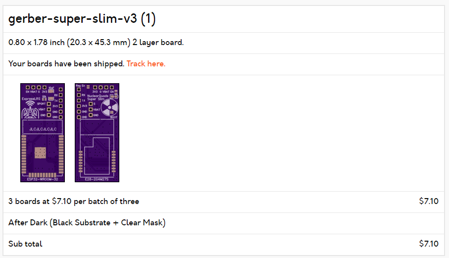
The original gerber files for PCB manufacturing can be found here:
https://github.com/ExpressLRS/ExpressLRS-Hardware/tree/master/PCB/2400MHz/TX_SX1280_Super_Slim
I have purchased all the electronic parts from Aliexpress as it was the cheapest source.
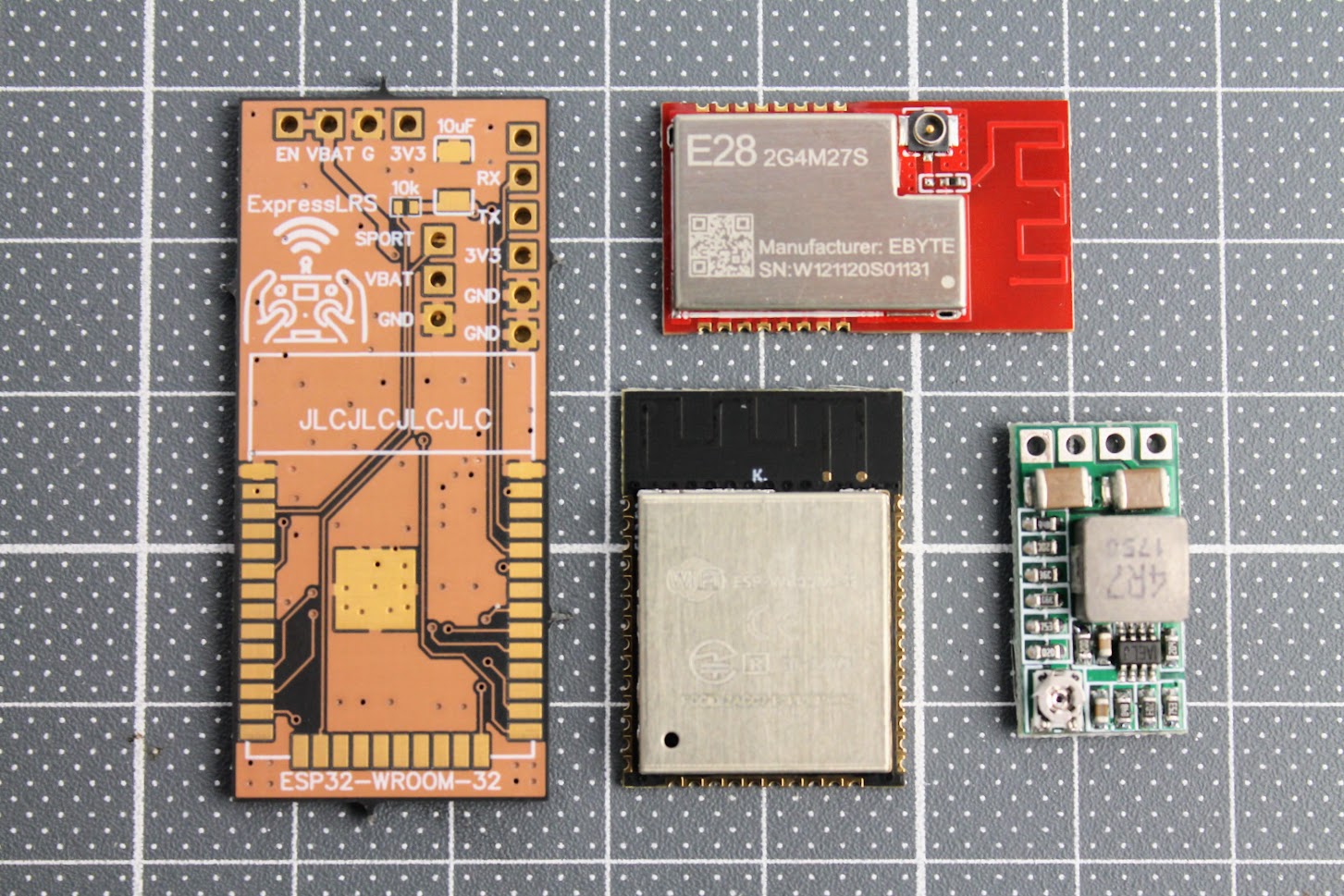
E28-2GM27S LoRa module (~$14) – https://www.aliexpress.com/item/1005001812234542.html
ESP-WROOM-32 module (~$5) – https://www.aliexpress.com/item/1005001833545594.html
DC-DC power supply module (~$2.5) – https://www.aliexpress.com/item/32880983608.html
SMA antenna pigtail (~ $0.5/pcs) – https://www.aliexpress.com/item/4000848776660.html
Also you will need 10uF SMD capacitor (3528 or type B size) and the 10k SMD resistor (0402 size).
Other things you will need: 5 pin 2.54mm header socket, silicone wires and of course a soldering iron set.
Build process
Soldered the ESP32-WROOM module and 10k resistor and 10uF capacitor. Soldering the resistor is the trickiest part as resistor is tiny (0402 size).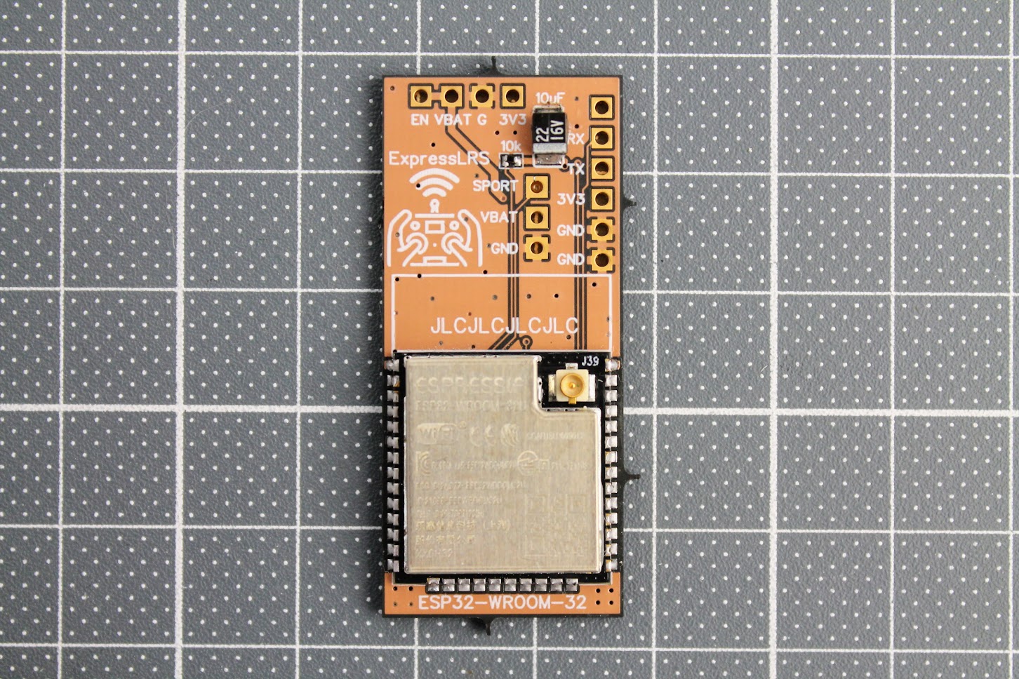
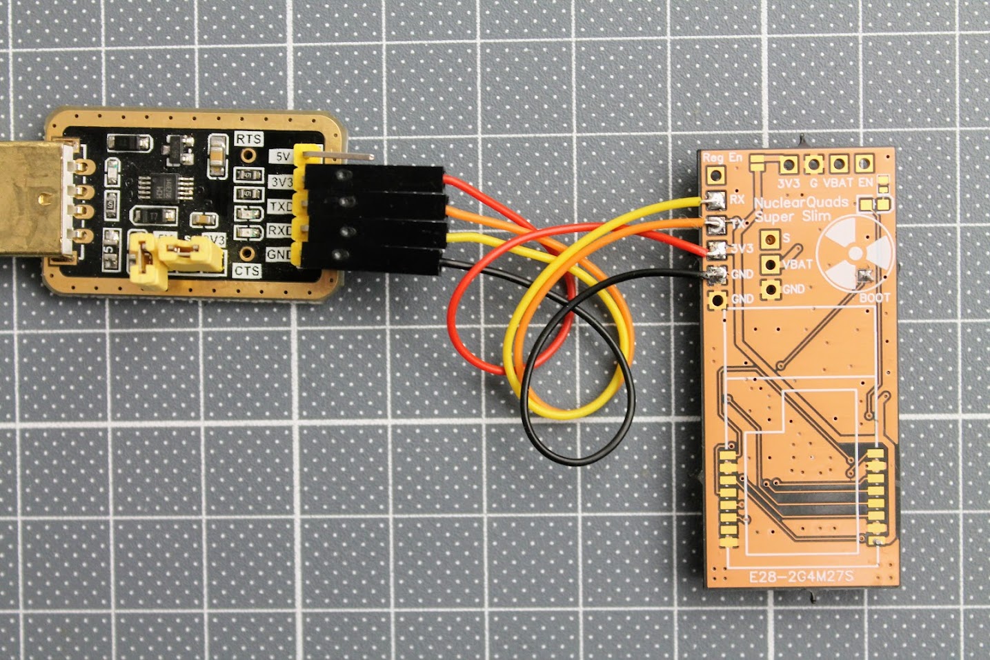
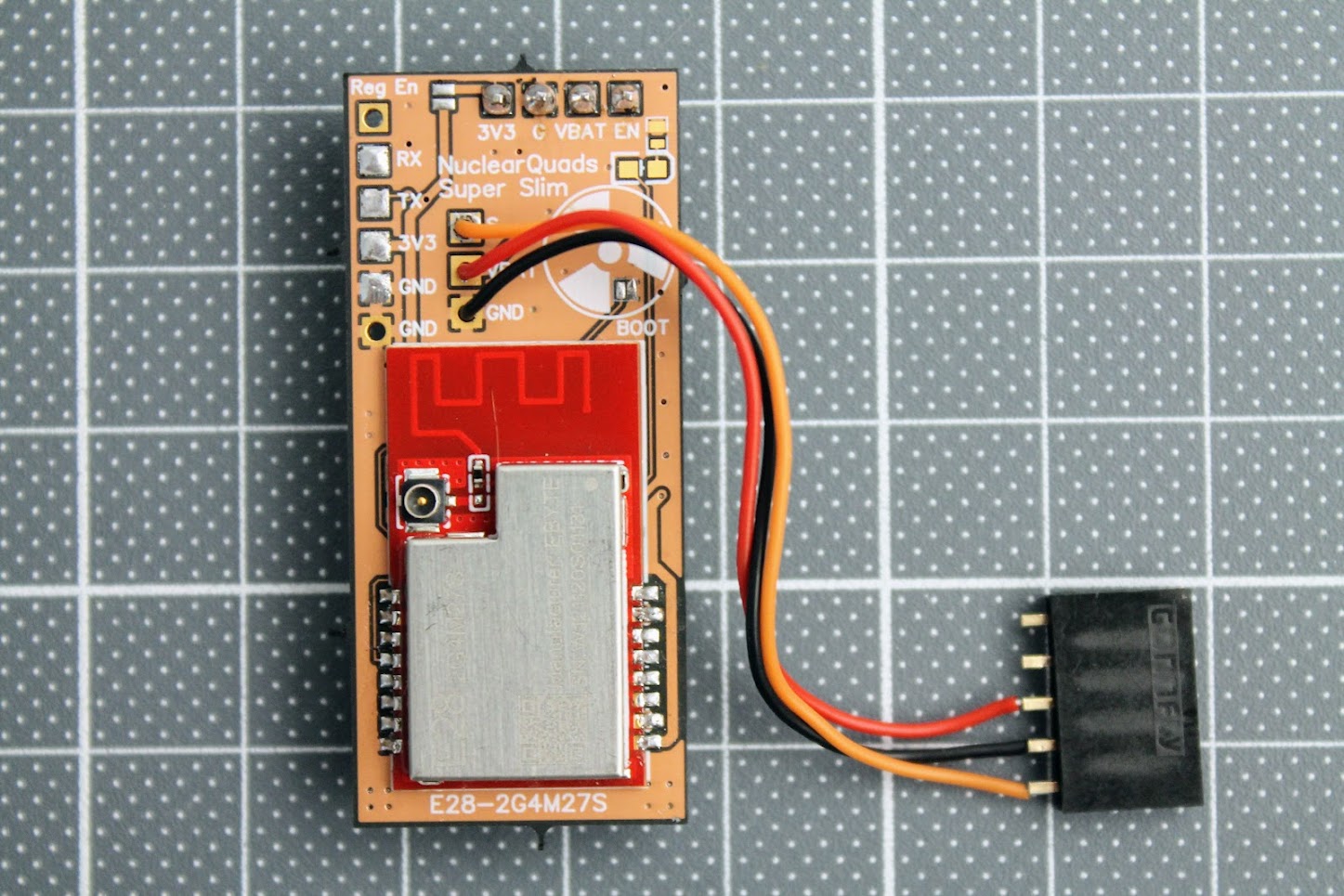
After the ESP32 module is soldered, you need to tempararily solder the RX, TX, 3.3V and GND wires. Connect these wires to the corresponding pins on the FTDI or any other USB to serial adapter. You can even use Arduino board. Don’t forget to short the BOOT pads for flashing the firmware by UART.
At this stage I would recommend to flash the ExpressLRS firmware to the ESP32-WROOM-32 module. For
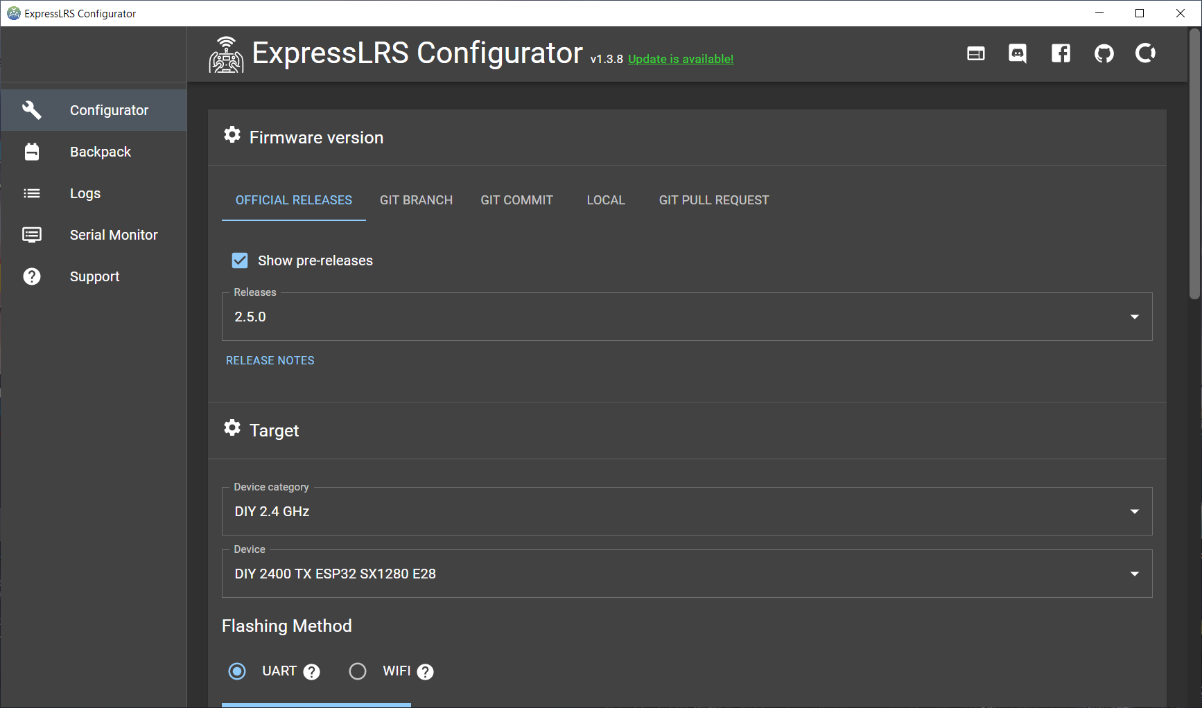
Start the ExpressLRS Configurator. You can download it from here: https://github.com/ExpressLRS/ExpressLRS-Configurator/releases/
Select “DIY 2.4 GHz” as Device category and “DIY 2400 TX ESP32 SX12800 E28” as Device.
Select UART as Flashing Method.
Read more about the flashing the ExpressLRS here:
ExpressLRS Open Source Long Range radio control system – Complete Guide
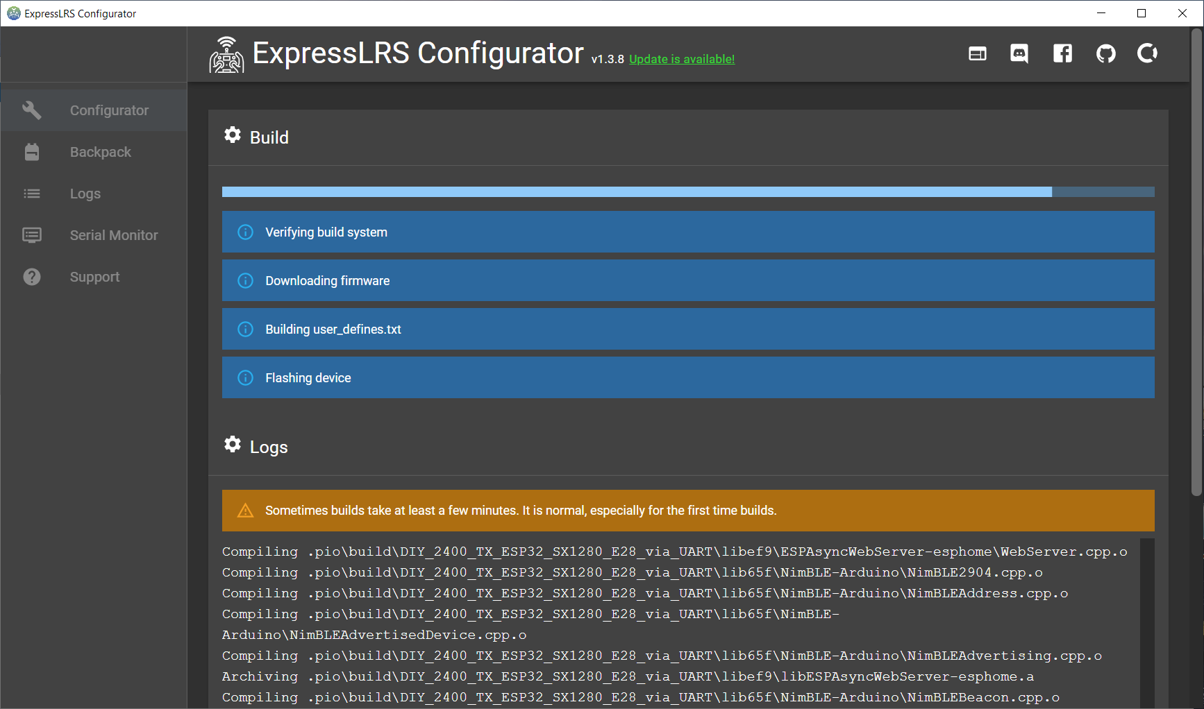
Press [Build & Flash]. Wait several minutes for it to compile.
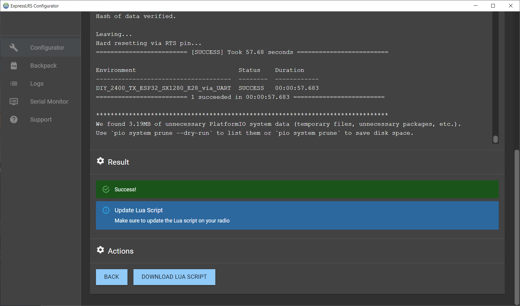
And flashing successful!
Now you can unsolder the FTDI (USB to Serial) adapter.
Next step solder the JR bay connector.
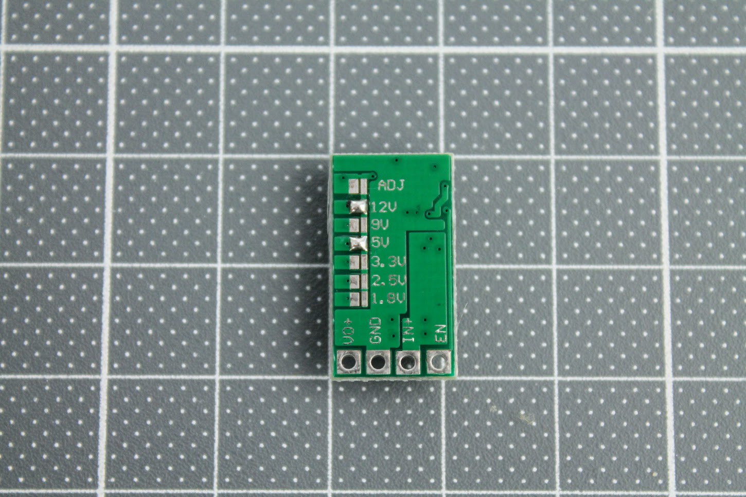
Prepare the power (voltage regulator) module. Short the 5V and 12V pads on the back side of the DC-DC regulator module. This will set the regulator to output the 3.45V, which is slightly more than 3.3V, but within the 5% tolerance of the modules.
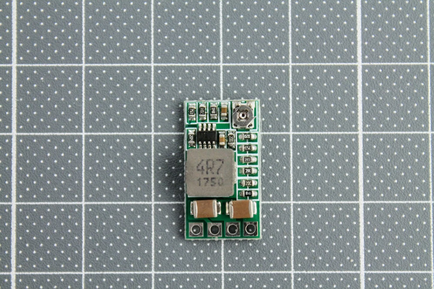
Turn the variable resistor to the clockwise end position (more about it below).
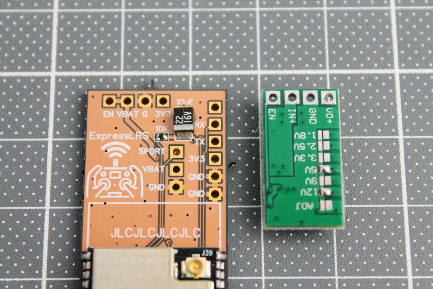
And solder the module to the EN, VBAT, G and 3V3 with the help of the pin headers.
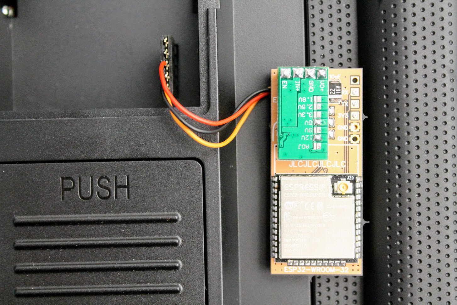
I also would like to suggest to connect the ExpressLRS module to the JR bay, power the radio, enable the External module in the model setup and measure the voltage between the GND and VO+ pads. It should be slightly more than 3.3V, the recommended voltage is 3.45V. In my case I have measured the voltage 3.58V, which is in the range of the absolute maximum voltage ratings (+10%) for the ESP32 and E28 modules, but its not recommended to operate the modules at this voltage, so I have turned slightly the dial on the variable resistor to set the 3.45V, which is 5% more than standard power voltage for modules. In theory E28 module should be happy to have a slight voltage overhead.
I need to notice, that at this point the ESP32 and E28 modules are not powered as the Reg En jumper pads are not connected.
Once the power voltage is set and verified, you can short the Reg En solder pads and solder the E28-2GM27S module.
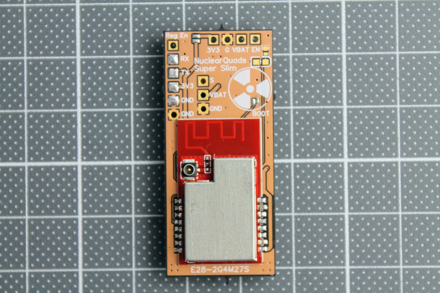
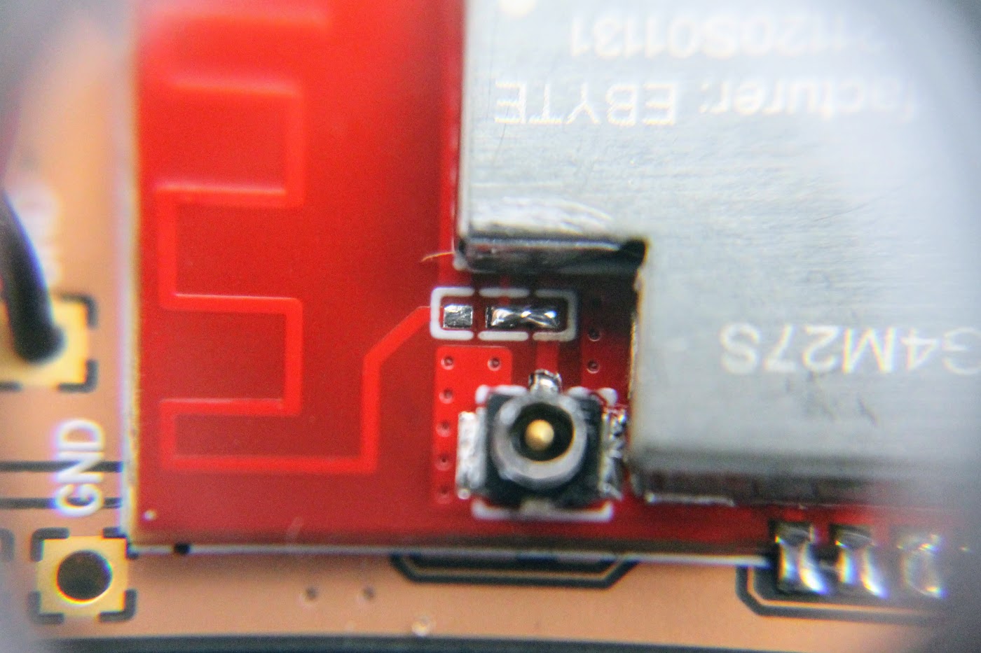
Another tricky part is to switch the zero Ohm resistor from the PCB antenna to the external (ipex) antenna position. I ended up just making the solder blob between the two pads as the resistor is zero ohms anyway.
Completely assembled with all the antennas connected. Notice that 3.3V power line Reg En jumper pads are soldered near the top right corner of the PCB board.
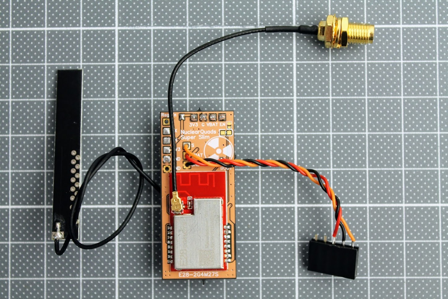
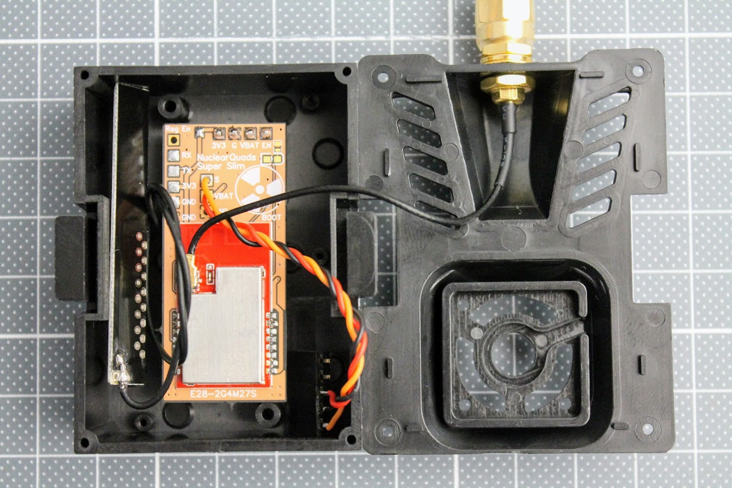
“Super slim” PCB variant of the ExpressLRS TX module fits easily in the JR case. Should also fit into the JR Nano case or even inside the radio as internal module.
Power output tests
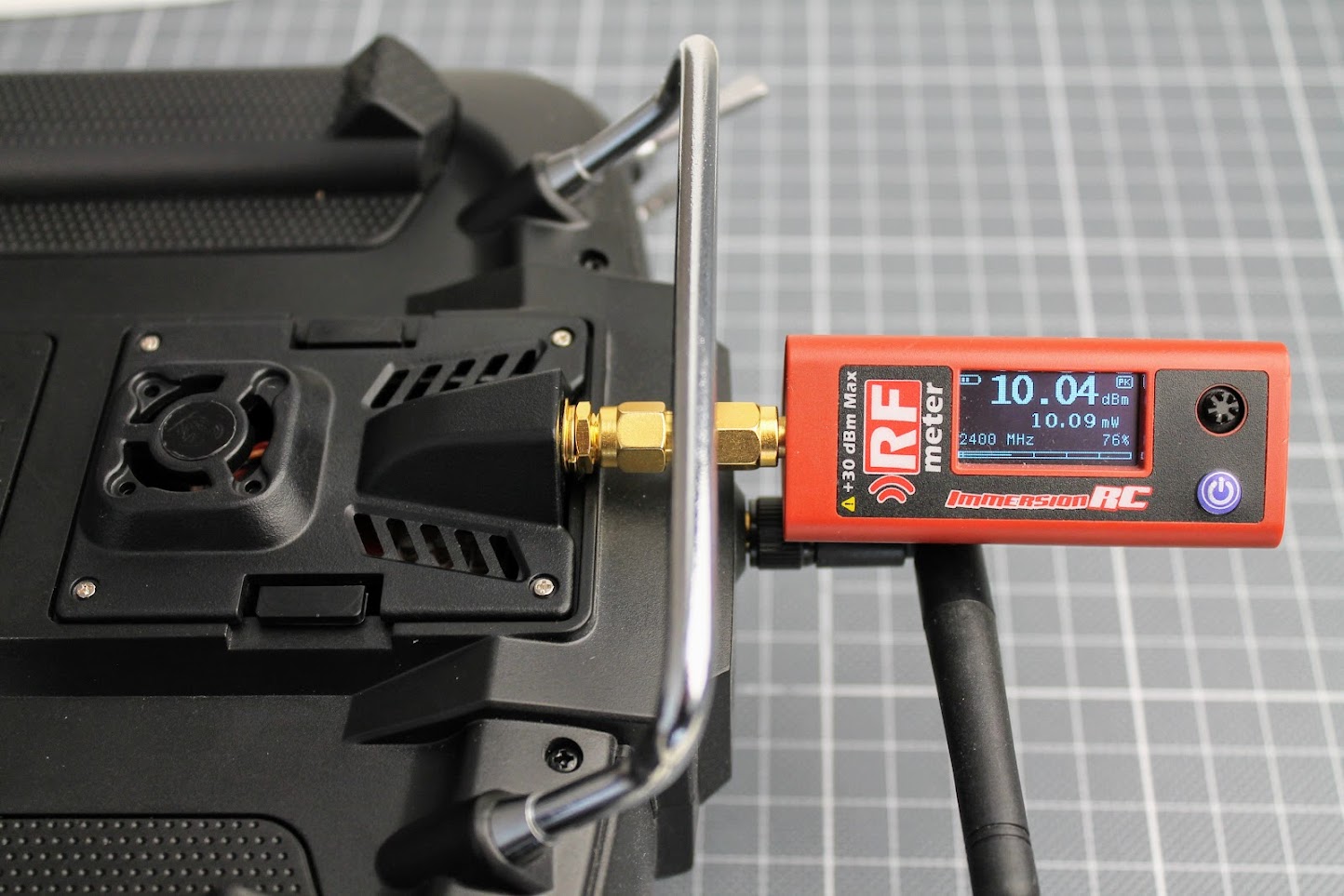
It is curious what RF power output does DIY ExpressLRS module gives. I have connected the ImmersionRC power meter to the antenna output of the DIY ExpressLRS module. The ExpressLRS module RF power output was set to 10mW, Dynamic power set to OFF. I’ve measured the exactly the 10mW of the power output.
At the 100mW output setting I’ve measured the 115mW output. 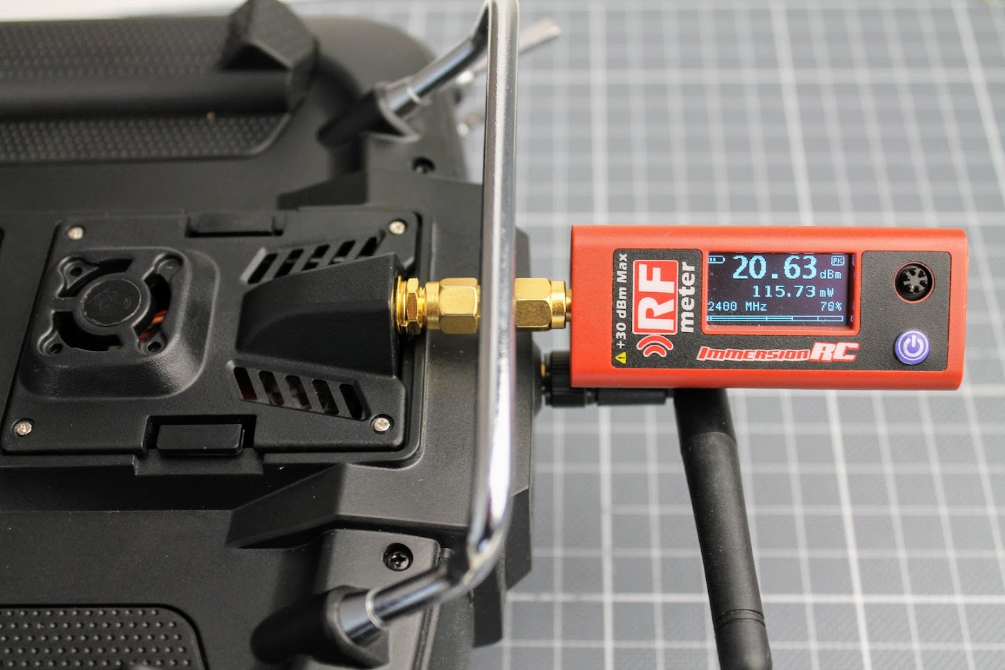
And at the 250mW setting my RF power meter measured 255mW of the RF output. 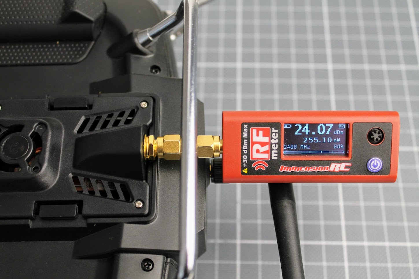
The 250mW output is stable, E28-2GM27S RF module does not heat up too much so no fan is needed.
DIY ExpressLRS Nano Receiver
Remarks
DIY ExpressLRS Nano receiver uses 0402 size components. They are small as 1.0 x 0.5mm (0.040″ x 0.020″). It is almost impossible or at least it is very hard to solder these components without hot air gun. You will need proper equipment and soldering skills for soldering this small RX.
RX Parts list
I have ordered the PCB on OSH Park (https://oshpark.com/shared_projects/yYtMC9D3). The cost of PCB was $3.00 for 6pcs. That’s $0.5 for one piece. Cheap as beans.
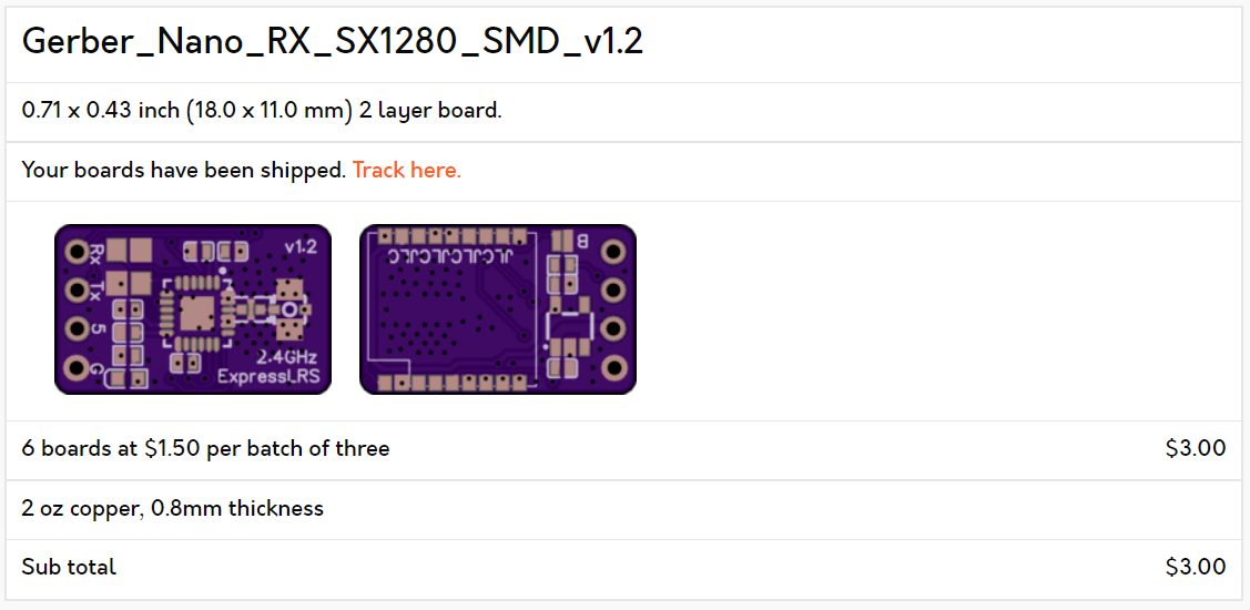
The original gerber files needed for PCB manufacturing can be found here: https://github.com/ExpressLRS/ExpressLRS-Hardware/…/PCB/2400MHz/RX_Nano
The EBYTE E28-2G4M12S module is used as the source for the cheapest SX1280 chip.
EBYTE E28-2G4M12S on Aliexpress: https://www.aliexpress.com/item/1005001808615493.html
ESP-01F module – https://www.aliexpress.com/item/1005001808615493.html
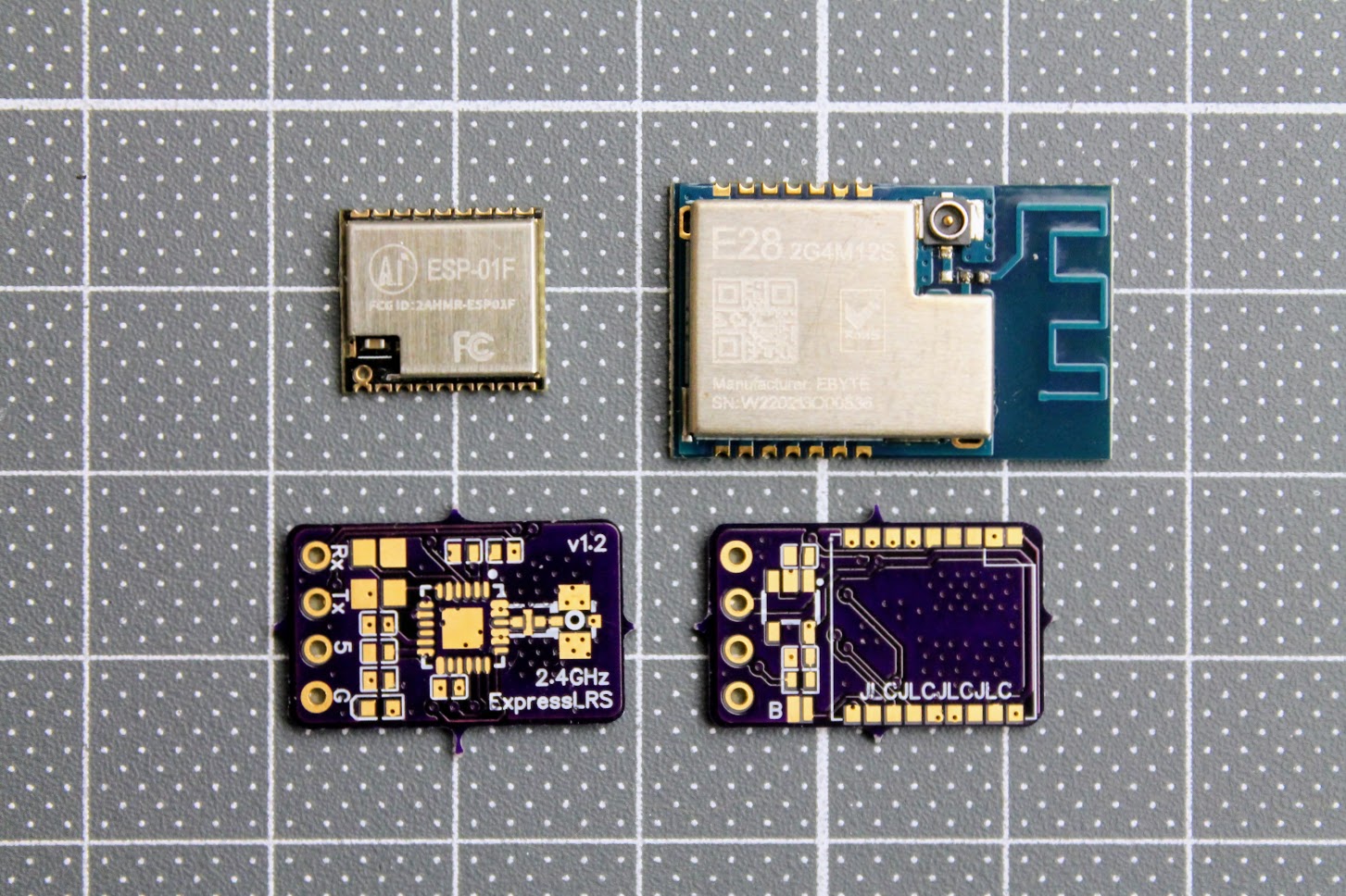
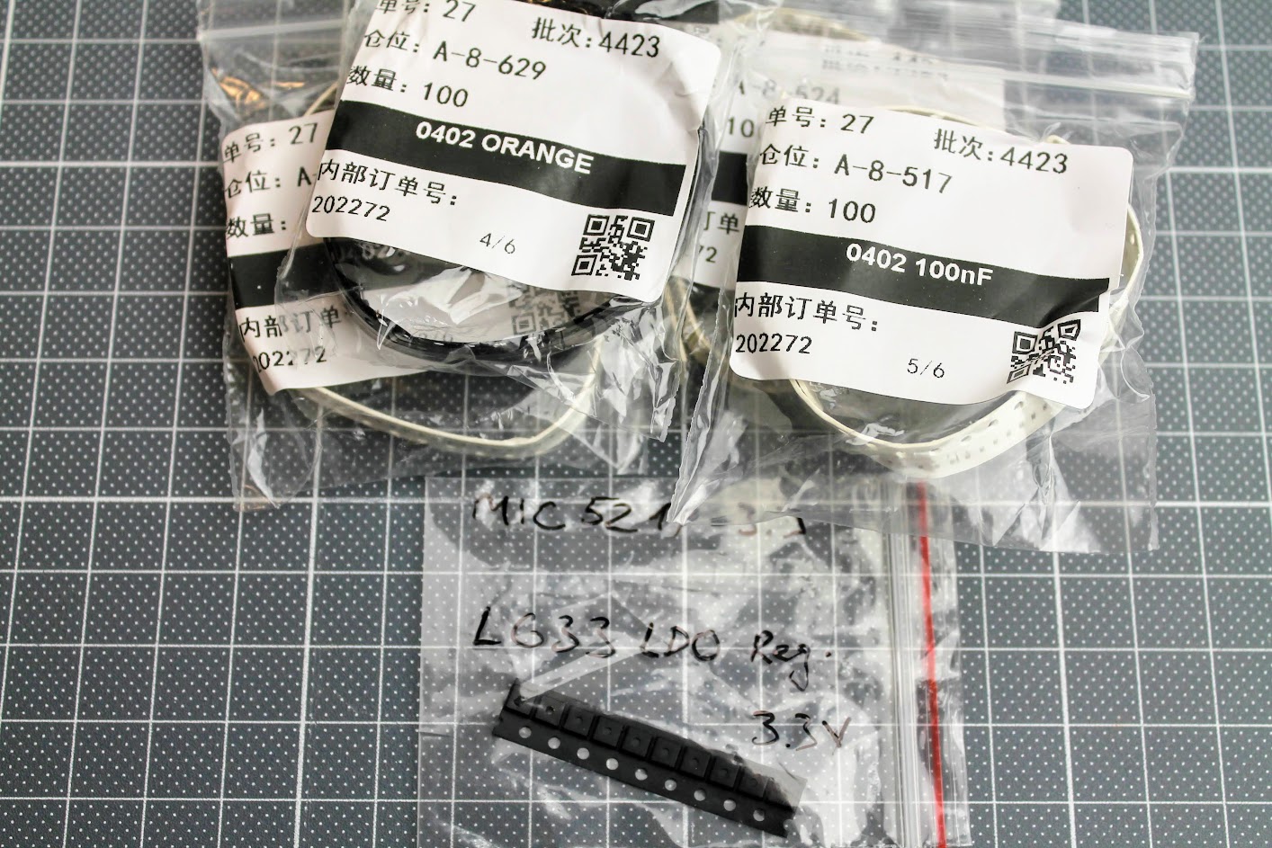
Some 0402 size components
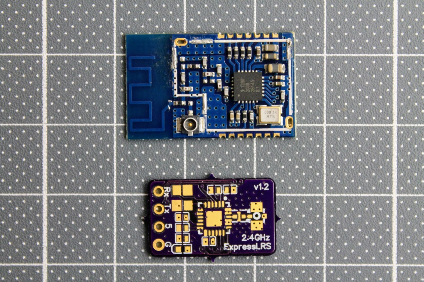
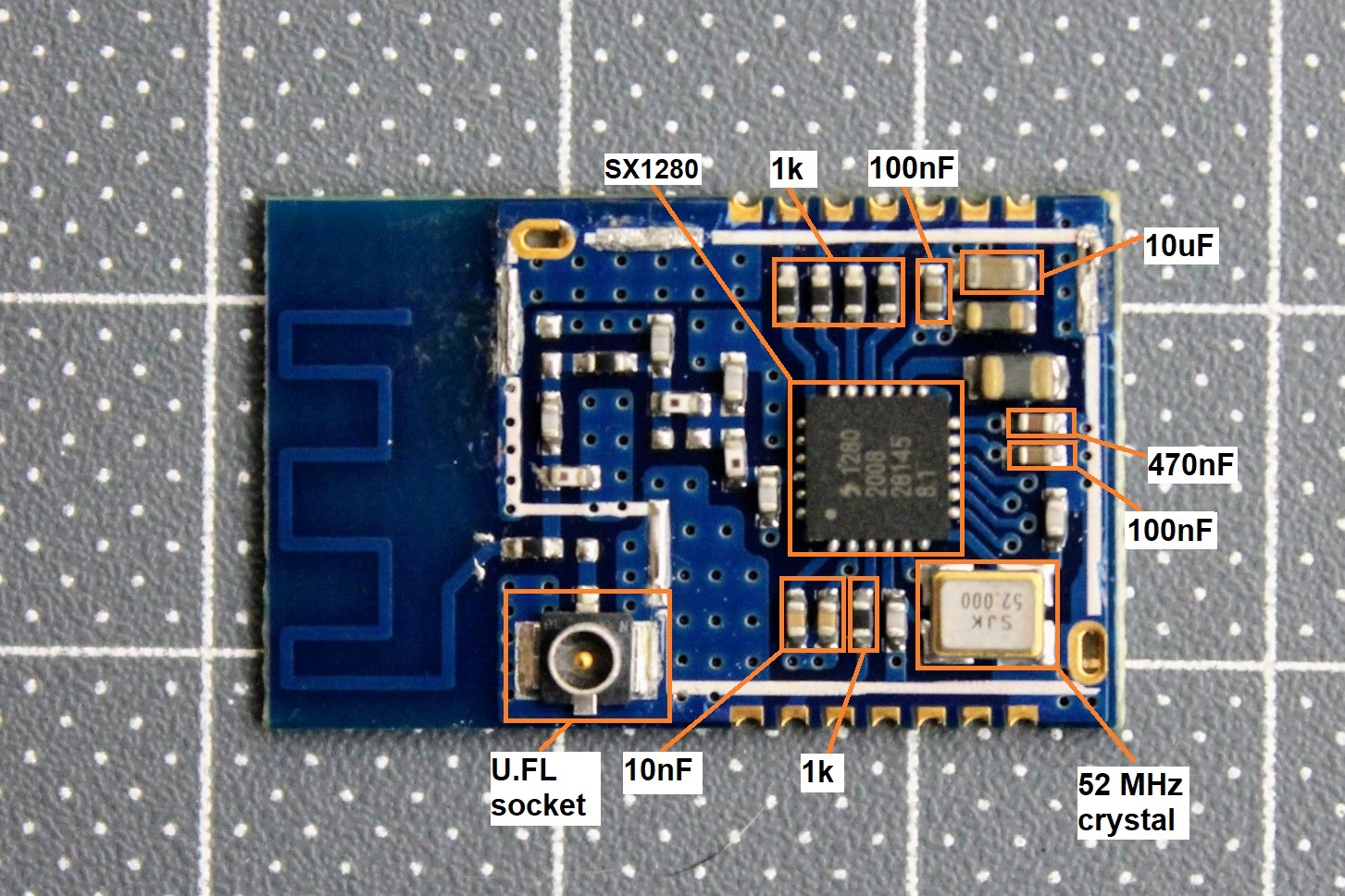
De-cased EBYTE E28-2G4M12S module.
Here is the diagram of the EBYTE E28-2G4M12S module components for reuse in ELRS receiver.
The only other components you need to get are:
0402 size LED diode, 0402 size 1uF and 2.2uF capacitors
MIC5219-3.3 or MIC5319-3.3 voltage regulator – https://www.aliexpress.com/item/33047428186.html
ESP-01F module – https://www.aliexpress.com/item/1005001808615493.html
2.4GHz low pass filter (ballun) – 2450FM07D0034T or 2450FM07A0029T. These are harder to get. Look for it on Mouser or DigiKey.
You will definitely need the RX antenna also.
Build process
The PCB and the components are so tiny, that you need definitely need the magnifying glass, hot air soldering gun, precision tweezers and SMD soldering paste. You will have to apply the soldering paste, place the SMD components on the back side of the receiver first, solder them with a help of hot air gun and then repeat the same on the top side of the receiver.
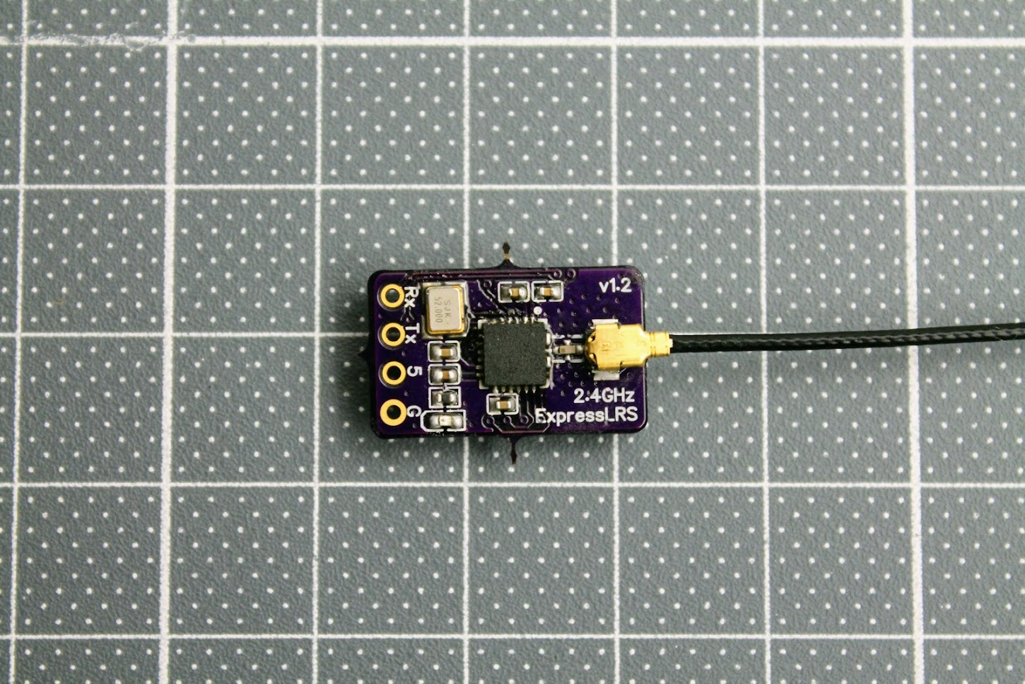
Photos of the soldered DIY ELRS Receiver.
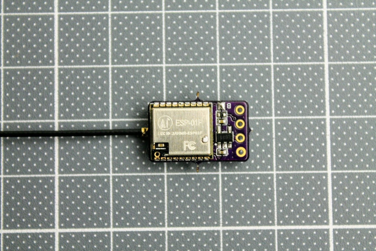
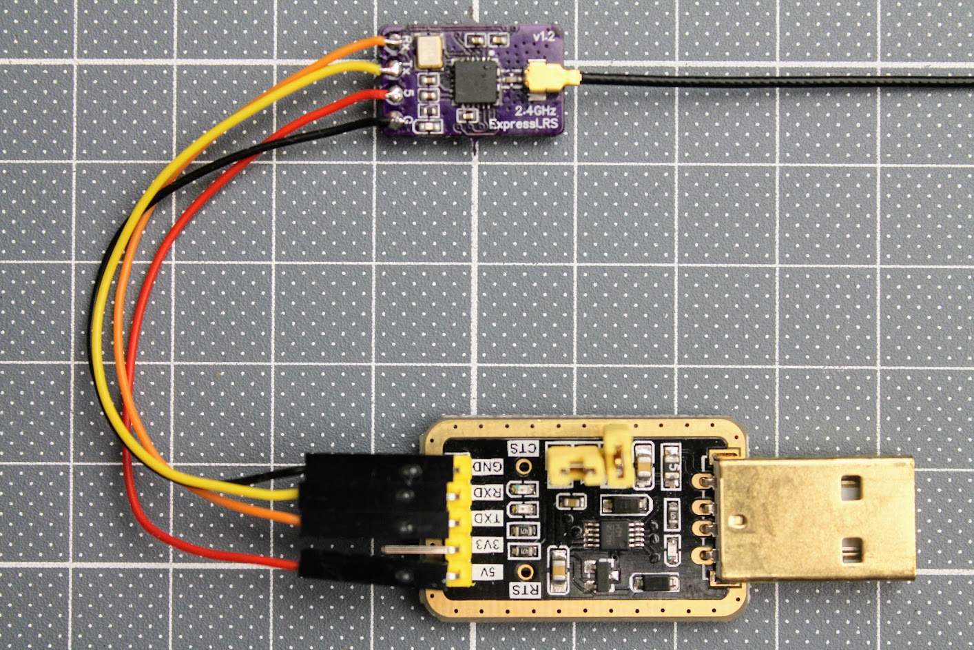
After the ESP-01F module is soldered, you need to solder the RX, TX, 3.3V and GND wires. Connect these wires to the corresponding pins on the FTDI or any other USB to serial adapter. You can also use Arduino Uno board for USB to serial adapter. Don’t forget to short the BOOT pads on the RX board for flashing the firmware by UART.
Read more about the flashing the ExpressLRS here:
ExpressLRS Open Source Long Range radio control system – Complete Guide
DIY ExpressLRS receiver ready for flashing.
Making the ExpressLRS transmitter and receiver by yourself is definitely a fun task, however you should evaluate your skills of the SMD soldering in case of the making the super small receiver.
-
 Review: MEPS Space SZ F7 Mini FC
MEPS (Mepsking) is a new, but emerging manufacturer, making its mark in the RC
Review: MEPS Space SZ F7 Mini FC
MEPS (Mepsking) is a new, but emerging manufacturer, making its mark in the RC -
 HGLRC Thor Pro parallel charging board
HGLRC Thor Pro charger board is battery parallel charging board with protection fuses and
HGLRC Thor Pro parallel charging board
HGLRC Thor Pro charger board is battery parallel charging board with protection fuses and
Why solder the 5v and 12v jumpers on the dc-dc power supply?
Soldering the 5V and 12V jumpers will set the regulator to output the 3.45V, which is slightly more than 3.3V, but within the 10% tolerance margins of the ESP32 and E28 modules. Slightly more voltage should help to output stable RF output on the max power setting.
Start making thousands of dollars every week. http://go.hojagoak.com/***
Not going to lift a finger unless you make it tens of thousands 🙂
Thank,s for schématic. But on the tx pcb, the resistor is 10K; on the list material 1K. What is the true value.
10k. I’ve fixed the list of the materials in the article.
Sorry i saw on Ghitub, the Value si 10k.
Thanks for notice! Yes, the actual value is 10k. 0402 size components are really hard to solder. Good luck!
Thank you for the article. What was your inspiration for creating the receiver and transmitter? I mean, maybe there is some kind of standard structure for these devices?
Thank you for your comment. There were several reasons for making the DIY TX and RX:
First reason – I was curious if I can make the working hardware, especially the tiny receiver with 0402 components. I was really surprised that the receiver worked right out after the first PCB was soldered!
Second – I was eager to test the power output of the DIY TX module with RF power meter. It turned out that power output is right on the specifications! Very good.
Third – I was going to make DIY TX/RX combo for my friend as birthday gift. Eventually he flew over 13km on 10mW power level with the same receiver as photographed in this article! Excellent results.
In general I’m very pleased with the process and the results. Since then I made a few more TX and RX with other designs that are even easier to build. I will be posting the new articles (or maybe just extend this one) with the new DIY stuff.
So I have question , TX part I configured (DIY 2400 TX ESP32 SX12800 E28) this
And receiver Section which device select in Elrs configrator for nano
I have flashed it with “Generic ESP8285 2.4Ghz RX” firmware. But there is no such option in the configurator any more. So you can try using the “BETAFPV 2.4GHz Nano RX” or “HappyModel EP1/EP2 2.4GHz RX” targets. They should be compatible. I have just tested the “BETAFPV 2.4GHz Nano RX” target and it works.
Can i use e28-2g4m27sx module? Seems like they are same difference is onboopcb antenna right?
Onboard pcb*
Yes, you can. Actually I would recommend you to use e28-2g4m27sx module as it has only the ipex socket and no modification is needed.