Review: Racerstar & Airbot AirF7 flight controller
Airbot, known manufacturer of the quality Flight controllers and ESC’s, and Racerstar, known brand of the Banggood, together released the F7 MCU based Flight Controller AirF7.
Specifications
Racerstar AirF7
Package contains the Racerstar AirF7 FC, silicone rubber grommets and 8-pin JST-SH 1.0mm cable for connecting 4in1 ESC board.
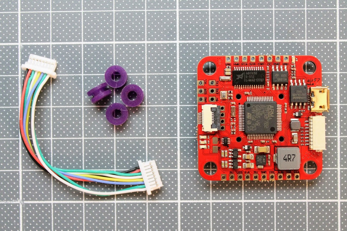
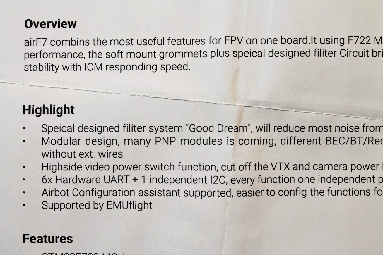
There is the user manual included in the package.
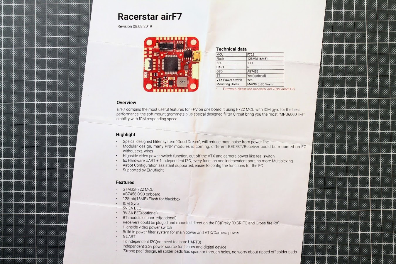
User manual is realy low quality, printed with some angle offset and with many spelling and grammar mistakes. I havent heared of such a thing as “Speical designed filiter system “Good Dream”” 🙂
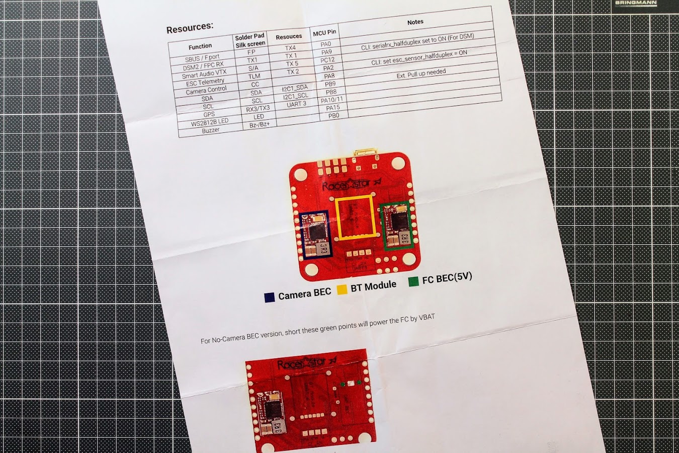
User Manual states that the BEC on the right is FC BEC (5V)
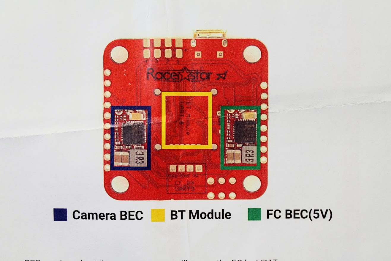
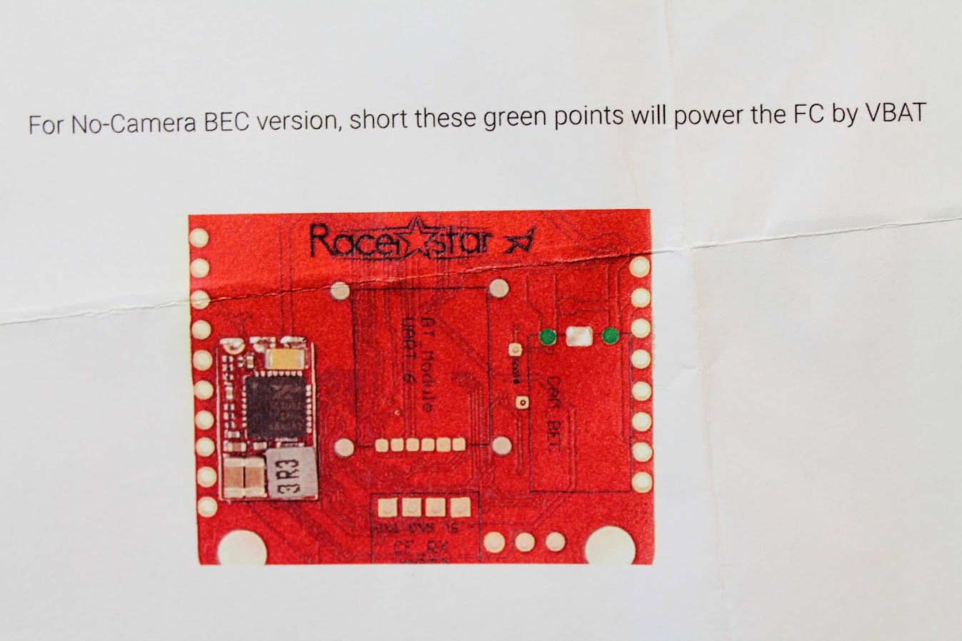
But in reality the right BEC is Camera BEC (9V). You can clearly see the markings CAM_BEC on the PCB:
Actually the AirF7 user manual is based on the Airbot F7 user manual, but Racerstar should have done it better.
Airbot F7 user manual: https://store.myairbot.com//media/iverve/uploadpdf/1561739006_80127-AirbotF7-0505.pdf
Racerstar AirF7 user manual: http://myosuploads3.banggood.com/products/20190909/20190909214037RacerstarairF7.pdf
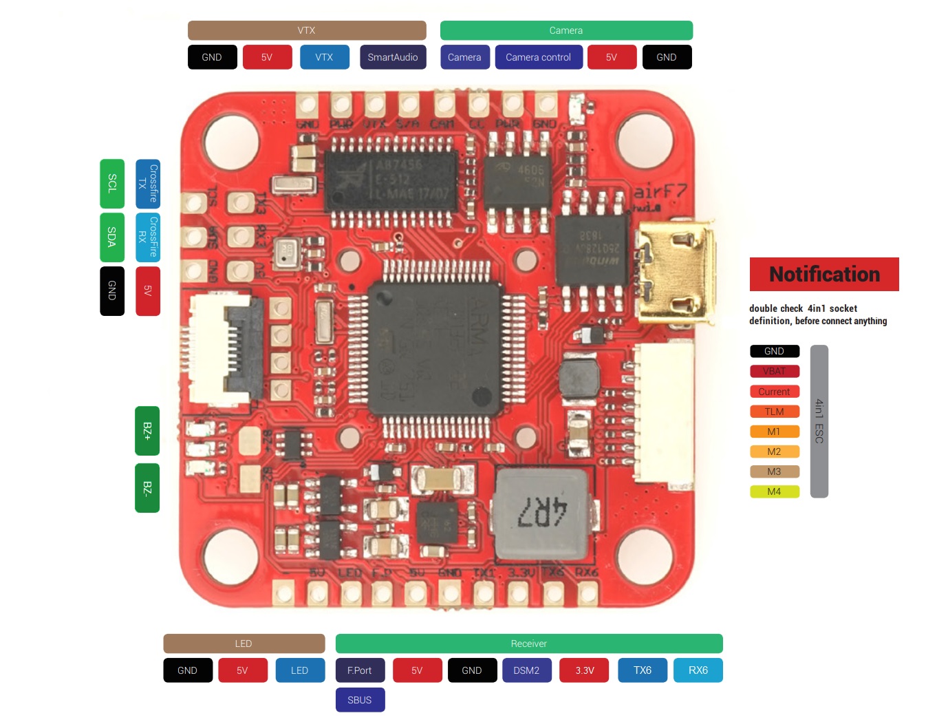
Also AirF7 user manual has no pinout information, so I have copied the pinout scheme from the Airbot F7 and made the Racerstar AirF7 board pinout scheme.
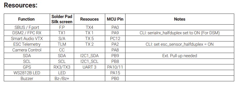
The resource table
Flight Controller in details
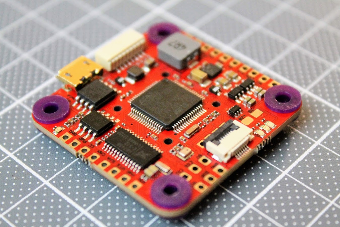
This AirF7 flight controller is stacked with features and surprises. Lets look at them.
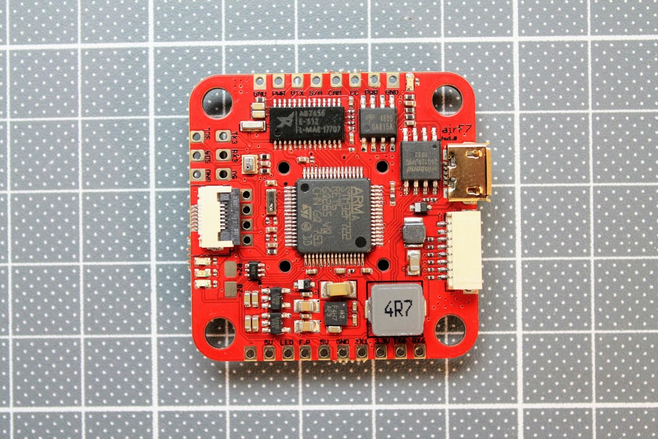
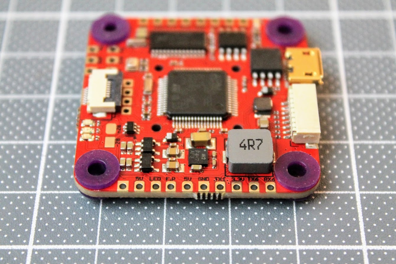
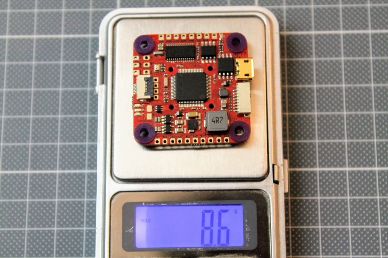
The view of the flight controller top side.
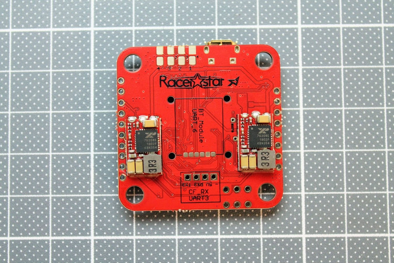
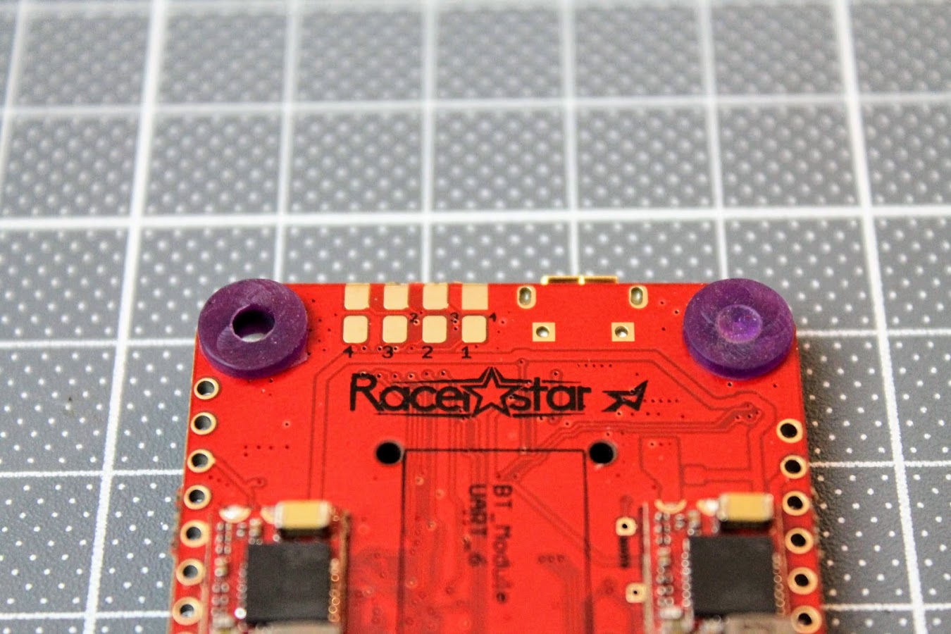
The view of the back side
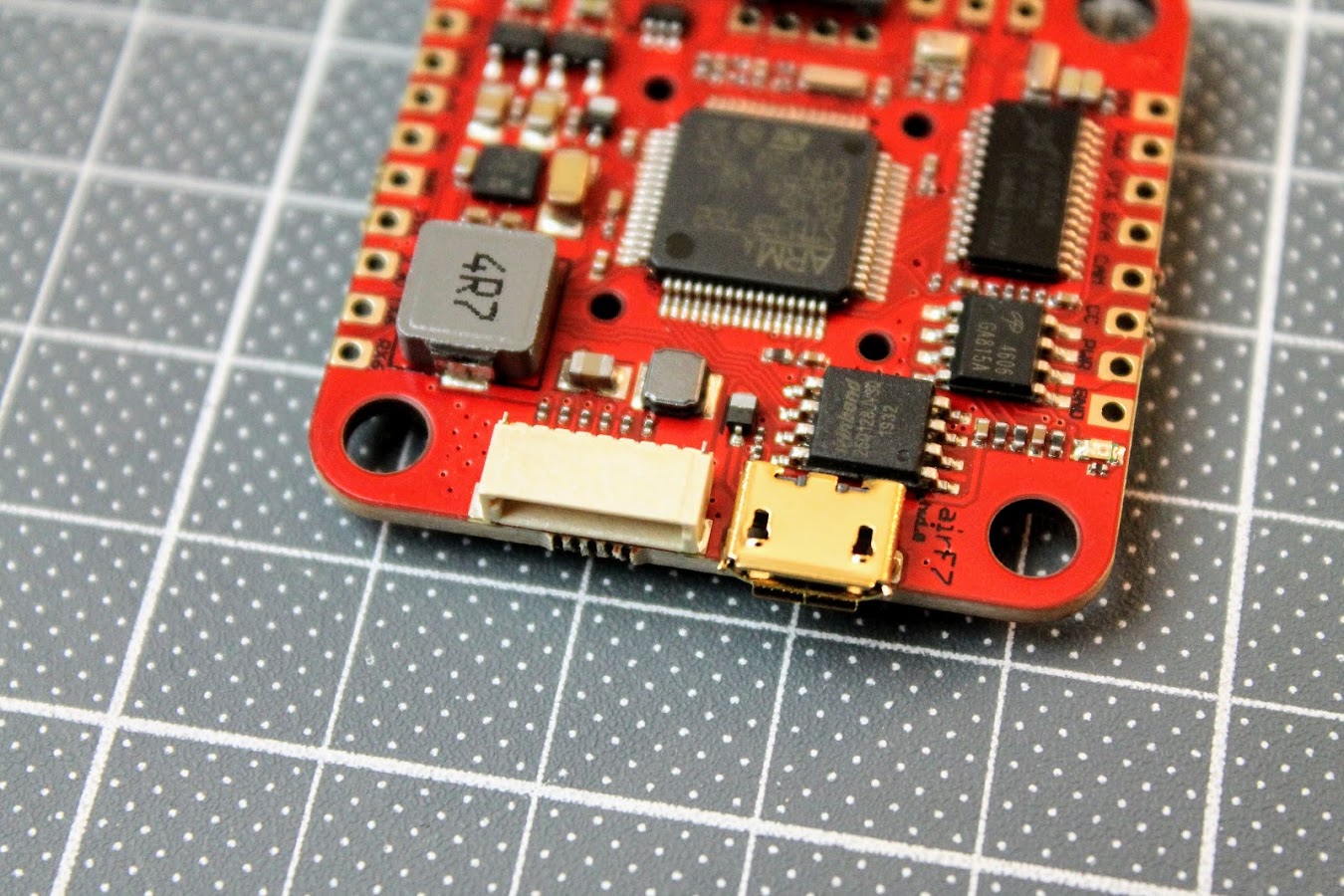
There is micro USB and 8-pin JST-SH 1.0mm socket for connecting to the 4in1 ESC on the right side of the board. You can find the pinout of the socket in pinout scheme above. There is BlackBox Flash 16MB memory chip right behind the USB socket.
Whole row of the pads for LEDs and UART 6 pads on the bottom part of the board. GND, 5V and LED control pads for programmable LED strips and lights. F.Port (Inverted) , 5V, GND, TX1 (uninverted) and 3.3V pads for connecting various receivers that need inversion (SBUS, FPort) or doesn’t need it. Also free TX6 and RX6 pads for UART 6 are available.
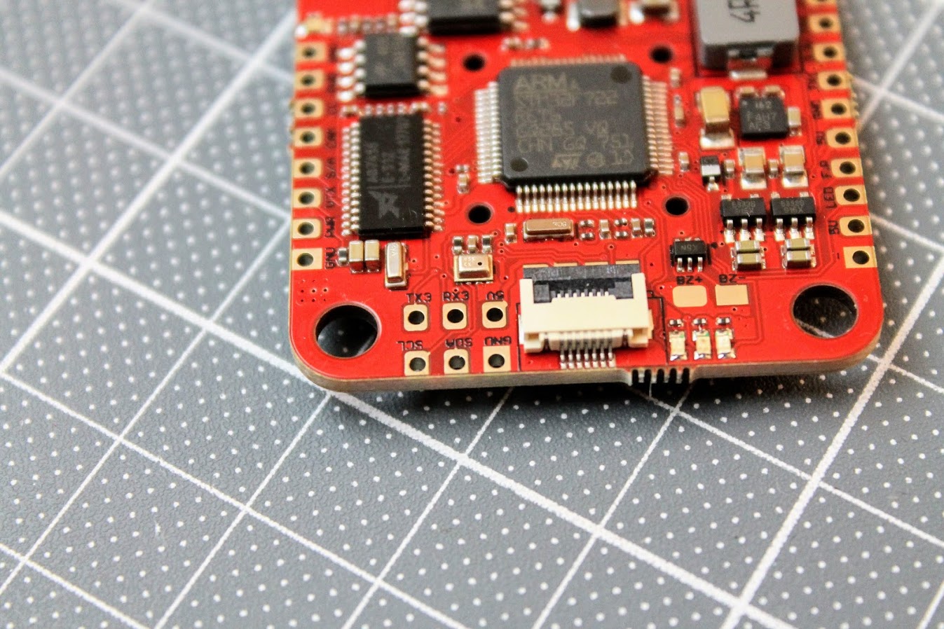
On the left side there are UART 3 pads and I2C interface pads. There is a undocumented Barometer on this FC, right behind the UART 3 pads! There are three status LEDs and buzzer pads. The connector in the middle is the SPI interface socket for connecting the External Gyro, R9MM-FC or RXSR-FC receivers.
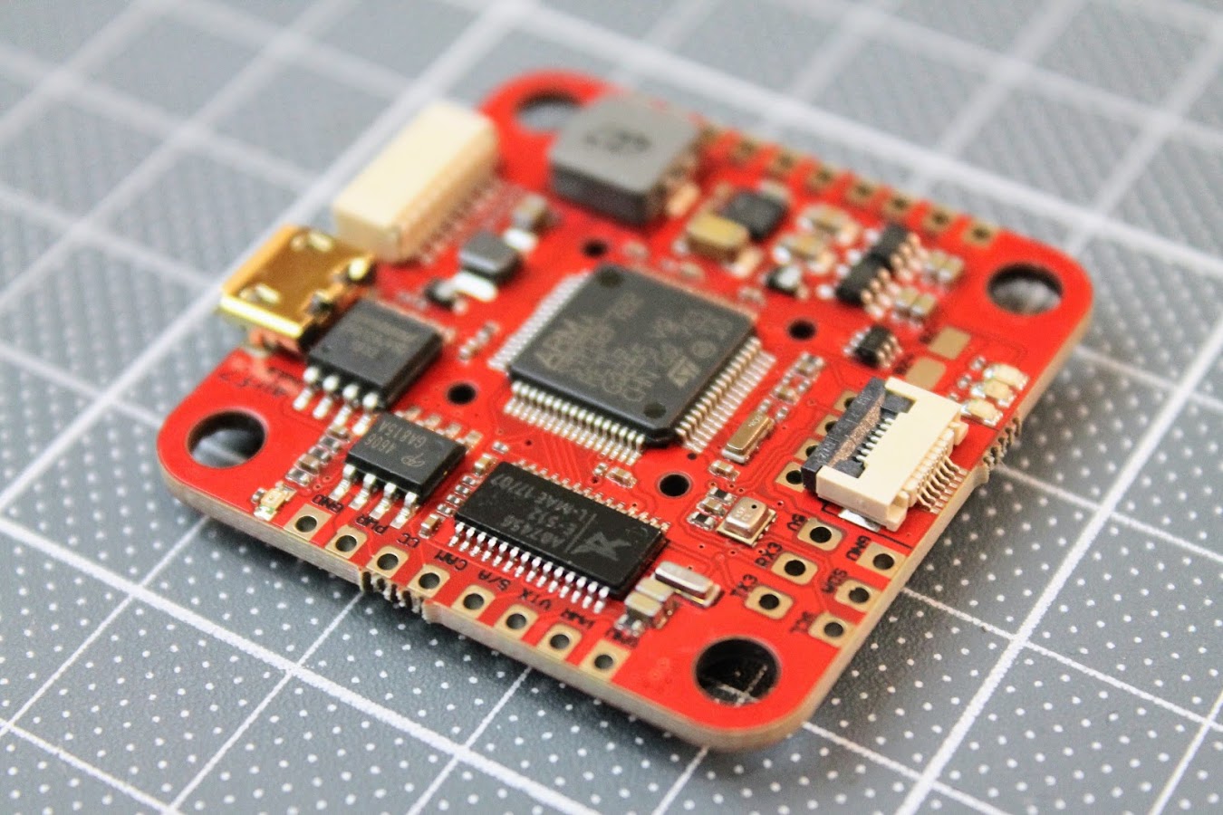
On the top side of the board there are Camera GND, Power, Video and SmartAudio pads. Also VTX GND, Power , CameraControl and Video pads. You can see Airbot AB7456 OSD chip behind the Camera pads and AO4606 Mosfet VTX power switch behind the VTX pads. The Airbot AB7456 OSD chip uses less power, is tolerant of wider voltage swings and twice as much nvram than the commonly used MAX7456 chip. There is LED indicator besides the VTX pads to indicate the VTX power status. LED is off if the VTX power is swithed off (VTX PIT mode).
On the bottom side of the board there are GND, +5 and TX3, RX3 pads for direct soldering the Crosfire Nano or FrSky XM/XM+ receivers.
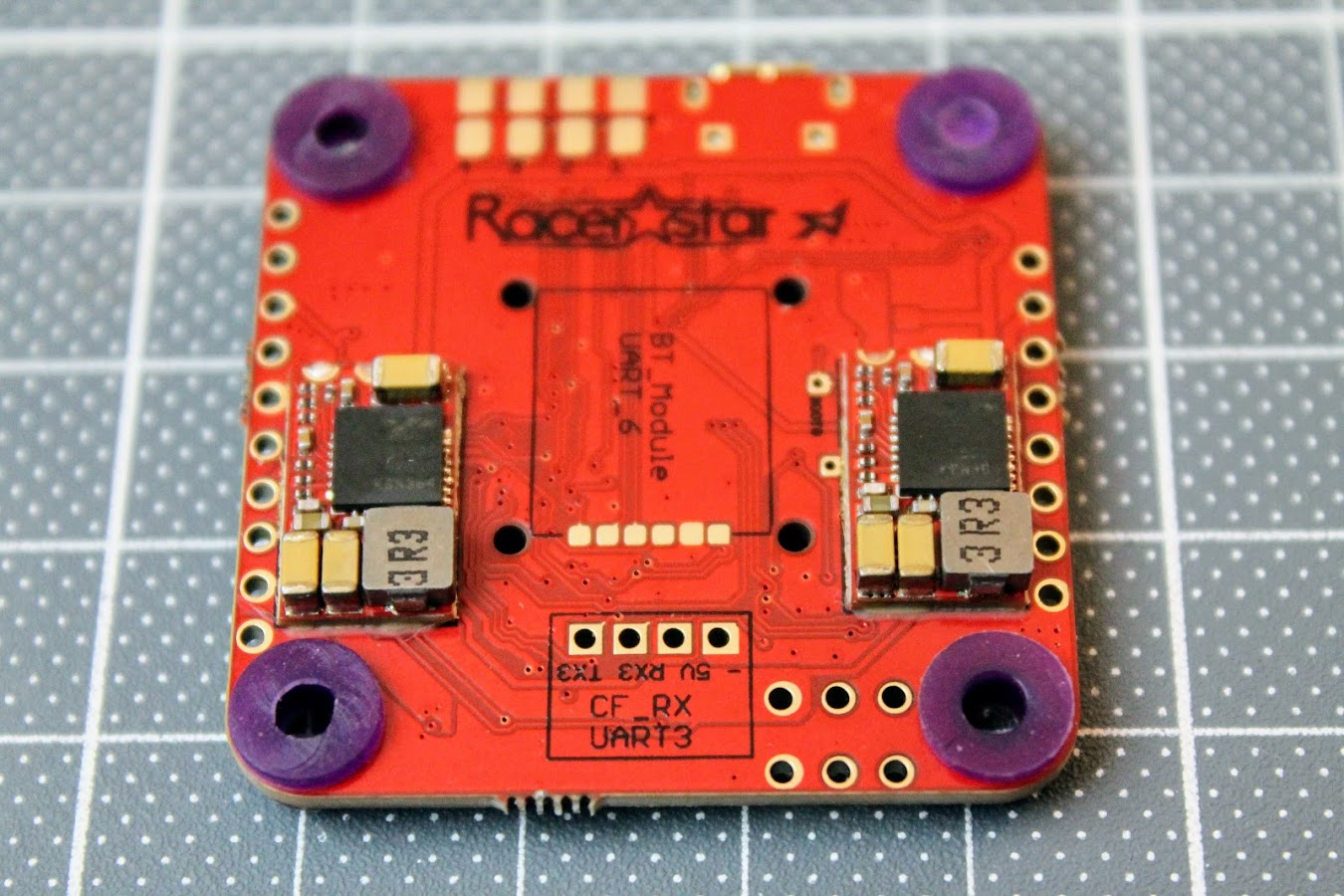
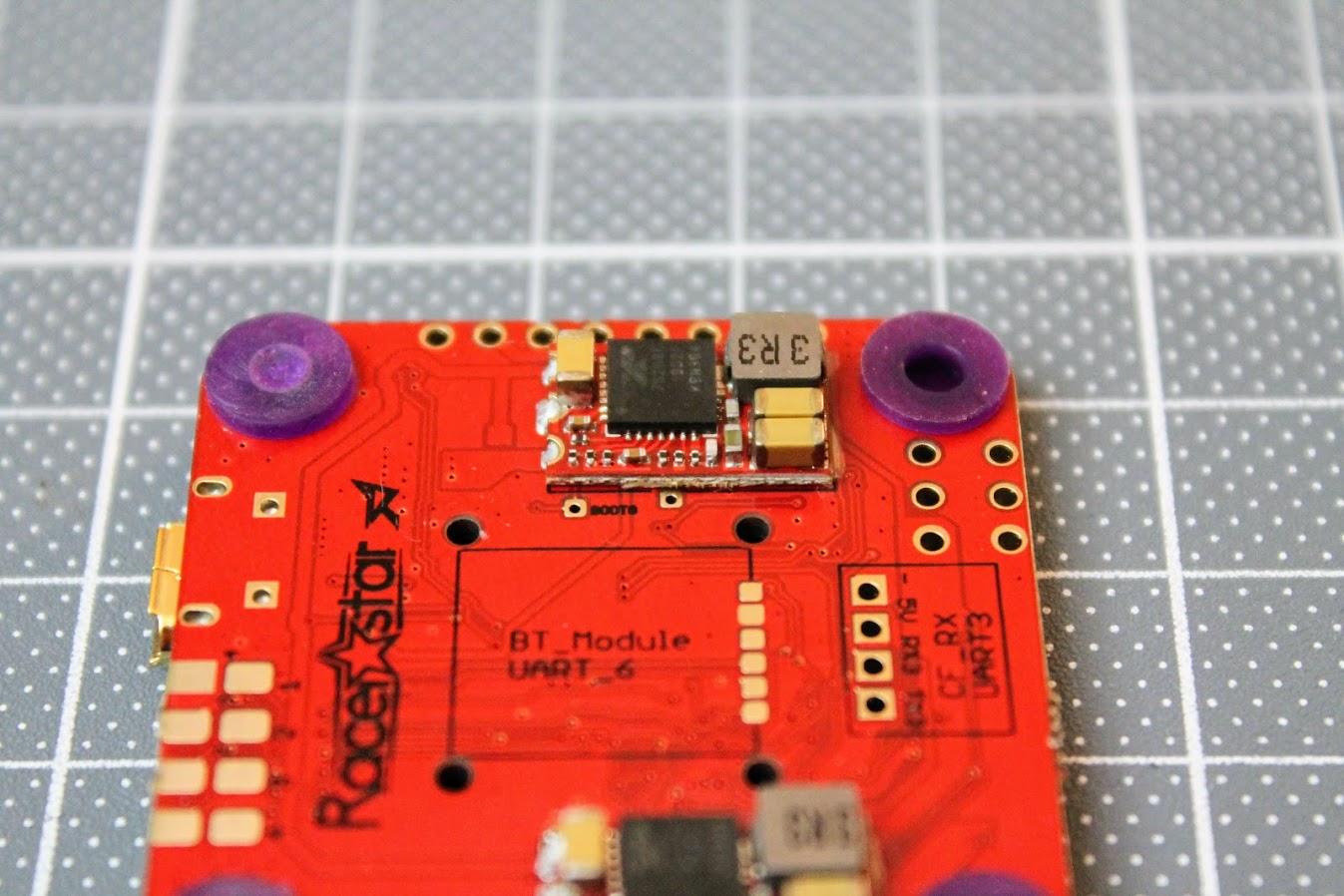
In the middle of the bottom side there is a place for soldering the optional Bluetooth module. It would use UART6 for the communication with
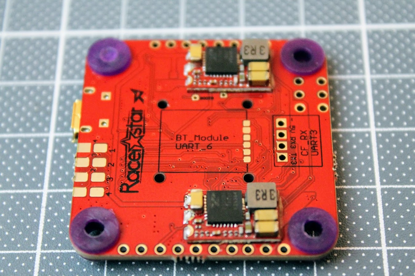
There are ESC solder pads in the normal and reversed order for soldering convenience.
There are Bootloader pads next to the 9V BEC, marked BOOT0.
Weight of the board is 8.6 grams.
Configuration
Racerstar AirF7 Betaflight target is AIRF7 (RAST) and is available from Betaflight 4.1.0.
There are some notes in the product page regarding the firmware, but I think these are outdated now:
Because the firmware is provisional, for 9V BEC there have 2 steps to switch on :
1. Please type in CLI as:
RESOURCE SERIAL_RX 4 NONE
set pinio_box = 40,41,42,43
aux 2 40 2 1600 2100 0
resource PINIO 1 A10
save
2. Then use AUX 3, and the range must cover 1500
we don’t know if betaflight can put this setting in the released firmware, but if it’s happened the 9V BEC not working ,you know how to resource .
Actually the board comes with RealPIT feature preconfigured on AUX3 channel.
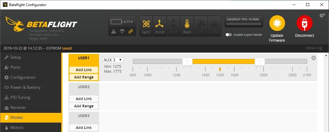
VTX power is switched on when AUX3 is in the range. You can adjust the range or AUX channel to your needs.
[To be continued]
Disclaimer: This item was supplied by Banggood for a fair and unbiased review. Banggood never asked for a positive review and never infuenced my opinion in any way. I’m trying my best to stay uninfluenced and give only my own opinion. All affiliate links if there are any help me purchase items for future reviews.
-
 Review: MEPS Space SZ F7 Mini FC
MEPS (Mepsking) is a new, but emerging manufacturer, making its mark in the RC
Review: MEPS Space SZ F7 Mini FC
MEPS (Mepsking) is a new, but emerging manufacturer, making its mark in the RC -
 HGLRC Thor Pro parallel charging board
HGLRC Thor Pro charger board is battery parallel charging board with protection fuses and
HGLRC Thor Pro parallel charging board
HGLRC Thor Pro charger board is battery parallel charging board with protection fuses and
Hi, and thank you for the review and the tips in this document! It already helped me when I couldn’t get power for the vtx and camera!
When I executed your commands everything worked, though I didn’t have to do this after I upgraded betaflight.
I’ve soldered everything up with an xm+ receiver, which I connected to the sbus port. I believe this is uart4. Though the led’s on the receiver indicate the binding was succesfull I can’t get any input in Betaflight. You’ve mentioned xm and xm+ receivers can be soldered to uart3. Is is possible the inverted signal from xm+ is causing the problem, and uart4 cannot handle this? I’m not sure if uart 3 is more convenient for diect soldering, or if it’s required to solder xm and xm+ receivers to this uart.
Thank you for the help.
SBUS/F.port should be connected to the F.P pad. This is UART4. I may have mixed things up in the article. Also check if the serial RX inversion is turned off
set serialrx_inverted = OFFHello everybody.
Anyone who owns this flight controller and wants to see a target on iNav, please support this request to create a new target on iNav
https://github.com/iNavFlight/inav/issues/7227
hello i need INAV in this FC 🙁
AIRF7 board is still not supported by iNav in 3.0.2. The iNav has “limited” number of the targets and developer is picky on the boards. Ask for the iNav support in the https://github.com/iNavFlight/inav/issues/7227